显示标签为“OM2 Multimode Fiber”的博文。显示所有博文

2014年6月8日星期日

The Introduction Of Bend Insensitive Multimode Fiber

Multimode optical fiber transmission performance is mainly limited by the phenomenon of DMD multimode fiber. Multimode optical fiber in the transmission during the pulse, an optical pulse broadening will diverge when such severe divergence condition to a certain extent, between the front pulse is superimposed on each other, so that the receiver can not accurately distinguish each of the optical fiber pulse signal, this phenomenon we called DMD (Differential Mode Delay).There are two main reason, first, the core refractive index distribution is not perfect. Multimode Fiber Cables DMD is the combined effect of the dispersion characteristic of the propagation time between the different radial positions of the incident pulse and the optical mode, the index multimode fiber refractive index profile can be designed well DMD characteristics. But DMD of refractive index profile is very sensitive to small deviations, and therefore it must be very precisely controlled in multimode fiber production, to achieve the perfect design values ??of the refractive index profile distribution. Second, the fiber central depression. A central depression is the refractive index of the fiber core center of decreased phenomenon. This recesses is connection with optical fiber manufacturing process. This will affect the transmission characteristics of the central depression of the fiber, the fiber properties decrease.

Therefore, precise control of the refractive index profile of the fiber and the elimination of the central depression is 10Gb / s Ethernet multimode fiber (OM3 fiber) R & D and production of the main tasks. MCVD and PCVD process is more suitable for the production of OM3 fiber preform. PCVD is the preferred method of manufacturing a multi-mode optical fiber having a number of layers deposited, precise control of the cross-sectional characteristics, the deposition process thousands layer can effectively control the doping amount of the deposited layer to obtain a refractive index distribution required to comply with the theoretical . While the process of collapsing, the recess etching amount by controlling the appearance of pore size can be avoided and the central hub.

10Gb / s Ethernet standard IEEE802.3ae get through, it will a 10Gb / s Ethernet market presented. Development in line with standard Gigabit Ethernet communication products is imperative. Long Fei, Draka, Corning, OFS have been successfully developed in line with TIA/EIA-4Array2AAAC standard 50/125mm laser optimized multimode graded-index optical fiber distribution products. Full bandwidth and DMD injection test results show that the 850nm wavelength, the optical fiber can support the transmission distance of 300 meters above the 10Gigabit network system. Meanwhile, the fiber also supports 10Gigabit Fibre Channel abd 10Gigabit of the OIF (Optical Internetworking Forum) standards, and is compatible with low-rate LED light transmission network.

With the rapid development of FTTx, a large multi-mode optical fiber into the interior, in the indoor environment and the narrow wiring, fiber is subjected to high bending stresses, especially in applications where long fibers are usually more compact wound storage box, it will be under a lot of fiber bending stress. With this, the attenuation properties and mechanical resistance to bending the cable put forward higher requirements. To solve these problems, bend-insensitive multimode fibers into being, similar bend insensitive singlemode fiber (G.657), it becomes a major field of research focus on multi-mode fiber.

In recent years, Draka, Corning, OFS has released OM3/OM4 bend-insensitive multimode fiber products. The fiber is compatible with the current conventional OM3/OM4 multimode fiber and optical fiber refractive index profile by optimizing the design, greatly reduces the fiber macrobend additional attenuation, minimum bend radius is generally up to 7.5mm. OM3/OM4 uses bend insensitive multimode Fiber Patch Cables in a way interior simplifies installation, reducing installation costs and reduce the risk of system interruption or failure. Since the bend-insensitive OM3 / OM4 multimode fiber has many advantages, once launched, it was favored on the market of all ages.

As we know, whether single-mode or multi-mode optical fiber, the numerical aperture (NA) is larger, the better its anti-bending performance. This is because the numerical aperture (NA) is greater, the difference by which the core and cladding refractive index is greater, the stronger the fiber waveguide ability. In a multimode fiber, the refractive index difference between the core of the fiber 62.5μm is twice the fiber core 50μm, and therefore the latter bending performance is poor, because the basic pattern of the fiber core 50μm Design is fixed, unable to improve its performance by increasing its resistance to bending refractive index difference. In the design of the fiber, due to lower Young's modulus of the inner layer of the coating material, the outer layer of the coating material to increase the Young's modulus is effective in improving the bending resistance properties. Furthermore, due to lower glass transition temperature Tg of the inner layer of coating material can be improved fiber bending properties at low temperatures. However, in order to more effectively improve the core 50μm anti-bending performance multimode fiber, the fiber must find a way out design from a structure (refractive index profile).

Bend-insensitive multimode fibers OM3/OM4 structure is similar to the standard multimode fiber, bend-insensitive multimode fibers (bend insensitive multimode fiber, BIMMF) the refractive index profile shown in Figure 12. Wherein the green line is a conventional 50μm multimode graded index profile of the optical fiber, blue and red dotted line for bend-insensitive optical fiber in two designs, the three-section of a multimode optical fiber shown in Figure 13. BIMMF distribution index profile, and the same in the core region 50μm conventional multimode fiber, only the ring groove is provided in the region depressed refractive-index cladding region near the core (called trench-assisted multimode fiber ). In conventional multimode fiber, when the fiber bend radius is too small, light intensity conduction mode will escape the core, causing signal distortion. In the bend-insensitive multimode fiber, the refractive index of the ring groove type subsidence area will form an obstacle to escape the intensity wakefield core barriers, thus effectively reduce the fiber macro bending loss.

Figure 12 50μm multimode fiber refractive index profile Multimode OM3 Fiber
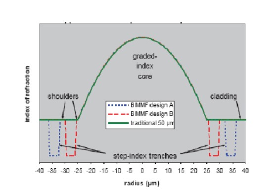
Figure 13 Conventional 50μm multimode fiber bend insensitive MMF, and two cross-sectional view BIMMF

 OM4 Multimode Fiber

The Multimode Fiber Proucts on market
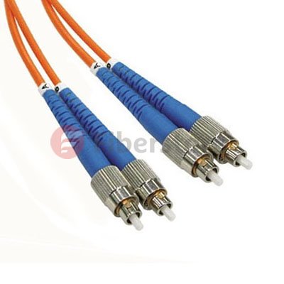
 FC-FC Duplex OM1

FC-FC Duplex 62.5/125 OM1 Multimode Fiber Patch Cable
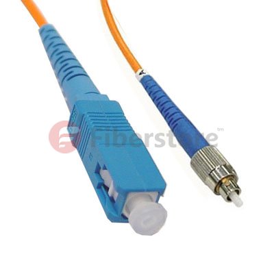
FC-SC Simplex OM2

FC-SC Simplex 50/125 OM2 Multimode Fiber Patch Cable

BIMMF bend-insensitive fiber mode field shown in Figure 14: In the conventional multimode fiber MMF, the guided mode in strong low conductivity state, and in close proximity to the core - cladding interface propagating order modes, because the effective refractive index neff close to the refractive index of the cladding n2, it is weakly conducting state (when the guided mode is equal to the effective refractive index neff cladding refractive index n2, the mode cutoff). Conduction state is weak order modes in the fiber bend radius is too small, its intensity will escape the core, causing signal distortion. In the bend-insensitive fiber BIMMF ring depressed trench type refractive index distribution has two light guide interface, the refractive index in the descending interface, the interface to form a light guide. Because of this interface, enhanced guided mode fiber core conductivity, so that the original order modes weak to lead the state into a strong lead state, shown in Figure 14. In addition, the external interface subsidence ring groove type refractive index distribution of the refractive index of small to large, the formation of refractive interface. Since the refractive index profile of this special structure, there is a leakage conductivity mode (leaky mode) in BIMMF fiber. Leakage mode is the solution of the equation in the intrinsic region outside the cutoff, leaky guided mode parsing mode is outside the cutoff continuous, their field is the same, but its intrinsic value, or the propagation constants are complex solutions Eigenequation, thus There are inherently leaky mode attenuation can not normally spread dissemination. The effective refractive index neff leakage mode of the cladding is less than n2. In the conventional multi-mode fiber, a leaky mode consumption decline rapidly, since the refractive index of a conventional optical fiber structure can not support its propagation in the fiber. And it BIMMF fiber, the refractive index in the form of this particular cross-sectional structure, a strong core to maintain close - cladding interface order modes propagating conductivity, thus effectively improve the flexural properties of the fiber.

2014年6月5日星期四

The Characteristics Of Singlemode and Multimode Fiber

Fiber is short for optical fiber, it is a new kind of optical waveguides, it is optical communication system that most common and most important transmission medium. It consists of a single glass core, the cladding layer close to the core, a primary coating layer and a protective layer composed of plastic cap.(Cylindrical fiber, the core, cladding and coating layers composed of three parts.) Core and the cladding layer consists of two different optical properties of the medium constituting the medium refractive index of light than the interior of a surrounding medium high refractive index. In the periphery of the package as the cover layer of opaque material, as the light is prevented from escaping from the surface during interspersed.

Multimode Optical Fiber

When the geometry of the fiber is much larger than the wavelength of light (about lμm), optical transmission process will be a significant presence of dozens or even hundreds of transport modes, such as the fiber is called multimode Fiber Optic Patch Cables.

Due to different propagation modes having different phase propagation velocity, thus, long-distance transmission is generated through mode dispersion (after long-distance transmission delay difference is generated, resulting in the optical pulse broadening). Side mode dispersion will narrow the bandwidth of multimode fiber, the transmission capacity is reduced, and therefore, multi-mode fiber is only suitable for low speed, short-distance optical fiber communication, data communication is currently a large number of multi-mode optical fiber local area network.

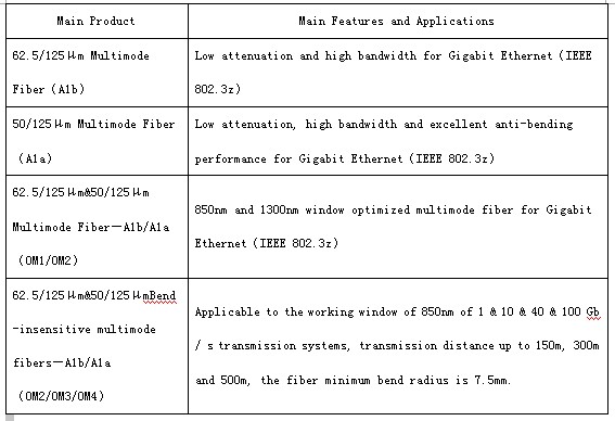
Main products and application performance of multimode fiber in the following
table:

 Multimode Fiber

The related products about 62.5/125mm Multimode Fiber Patch Cable from fiberstore.com, it is below:
Duplex OM1 62.5 125  Fiber Patch Cable
  The product about 50/125mm OM2 Multimode Fiber
  Duplex OM2 50 125 Fiber Patch Cable
Single Mode Fiber Cable

When the geometry of the fiber is small, and the wavelength of the same order as the core diameter in the range of 4-10μm, the optical fiber allows only one mode (basic mode) in which the transmission, the remaining high-order mode are all turned off, so that said Single Mode Fiber Cable. Avoid the mode dispersion single mode fiber, suitable for large-capacity long-distance transmission.

IEC 60793-2 and IEC 60793-2-50 singlemode fiber will be divided into B1.1, B1.2, B1.3, B2, B4, B5, B6 and other categories, ITU-T also G.652, G .653, G.654, G.655, G.656, G.657 and other recommendations were standardized definition and characteristics of various single-mode fiber, and each part of the GB / T 9771 with reference to IEC 60793-2-50 ITU-T G.65x series formulation.

A given type of single mode fiber, the mode field diameter by (also called effective area), the dispersion coefficient, dispersion slope, wavelength cutoff adapted to optimize the parameters, and access ways for different applications.

2014年5月25日星期日

Key Technologies And Development of Multi-mode Optical Fiber

Corning and Lucent and other large companies proposed a "new generation of multi-mode fiber" concept to the international standardization bodies. A new generation of Multimode Fiber Patch Cable; standards drafted by the International Organization for Standardization / International Electrotechnical Commission (ISO / IEC) and the Telecommunications Industry Alliance (TIA-TR42). As a new generation of multi-mode fiber transmission medium 10Gb / s Ethernet, be included in IEEE 10Git / s Ethernet standard. This article will briefly describe the new generation of multi-mode fiber critical technical information.

1.1

The Typle of New Generation of Multimode fiber

The new generation of Multimode Fiber Cable is 50/125μm, graded-index multimode fiber distribution. The number of this transmission mode Fiber Optic Cables is approximately 62.5μm multimode fiber transmission mode 1/2.5. This can effectively reduce the dispersion of the multimode fiber mode, increase the bandwidth. For 850nm wavelength, 50/125μm Multimode fiber bandwidth is 500MHz.km. Recent experiments confirmed: the use of 850nm vertical cavity surface emitting laser (VCSEL) as a light source in the 1Gb / s rate, 50μm multimode fiber core diameter standard error can be no transfer 1750m, 50μm core diameter multimode fiber can be a new generation of error-free transmission 2000m. In the 10Gb / s down, 50μm core diameter multimode fiber can transmit a new generation of 600m. A new generation of multi-mode fiber is mainly used to support high-speed Ethernet (Ethernet), Fibre Channel (FC) and fiber optic interconnection (OIF). Meanwhile at 10Gbit / s system can transmit 600m, so that it can be used for building backbone and campus backbone extraordinary distance from the middle. In the data center design, within a distance of 100m to support higher speed (40G and 100Gbits / s? Ethernet, 16G and 32Gbits / s Fibre Channel) data transmission requirements.

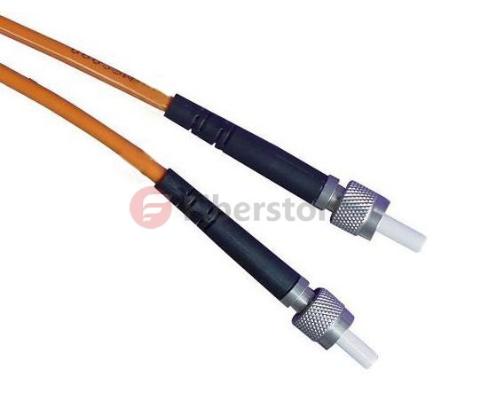
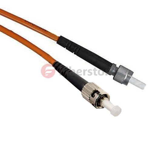
The related products about New Generation Multimode fiber, SMA905-ST Duplex 50/125 Dia2.5mm OM2 Multimode Fiber Patch Cable from fiberstore.com, the products picture is below:

OM2 Multimode Fiber
The SMA-905 fiber optic patch cord, also known as FSMA connector, was one of the First fiber optic interconnect system that gained industry wide acceptance.SMA905 fiber patch cords make use of threaded connections and is still widely used for military, industrial, medical and Surgical applications and laser systems because of their low cost multimode coupling. It features simple termination and Assembly, and is TIA and IEC compliant. SMA 905 multimode connectors are available with stainless alloy or stainless steel ferrules.

1.2 A New Generation of Multi-mode Fiber Source

Traditional multimode fiber networks use light-emitting diode (LED) as light source . In low-speed network, which is an economically rational choice. However, LED is spontaneous emission light, the radiation -emitting laser is excited , the carrier lifetime is longer the former than the latter, and thus the LED modulation rate is limited , and not more than gigabit networks. Further, LED compared with a laser, the beam divergence angle, wide spectral width . After injection of multimode fiber , excite more high-order mode, the introduction of more wavelength components, so that the fiber bandwidth decreases . Fortunately 850nm vertical cavity surface emitting laser (VCSEL) not only has the advantage of these lasers, but aslo the price is basically the same with the LED. Other advantages of VCSEL are: low threshold current, may not be enlarged, driven directly by logic gates at 10Gb / s rate, get a few milliwatts of output power; emission wavelength of 850nm which does not apply to the standard single-mode fiber just for multimode fiber . At this wavelength, an inexpensive silicon detectors can be used and have a good frequency response; VCSEL another remarkable advantage is that the manufacturing process can be easily controlled distribution of the emitted light power , which is very advantageous for improving the bandwidth of MMF. It is because of these advantages, the new generation of multimode fiber standard will use 850nm VCSEL light source.

1.3

The Bandwidth Distance of New Generation Multimode Optical Fiber
By comparing the above- described laser and LED , the use of multimode fiber laser light source, the transmission bandwidth should be greatly improved. However, experimental results show that simply make the bandwidth of a laser instead of LED light source, system is not only reduced but increased. IEEE Expert Group found through research, the bandwidth of multimode fiber and the optical fiber or the injection molding state of a power distribution. The preform fabrication process, the refractive index of the fiber axis prone to depression. Done before light source LED, is overfilled launch (OFL-Over Filled Launch), all of the fiber mode ( hundreds ) are excited to bring their own part of each module power. The refractive index of the fiber center delay characteristic distortion affects only a small number of models, the relatively limited impact on the modal bandwidth of the fiber. The measured multimode fiber bandwidth for the use of LED light source system is correct. However, when a laser light source, a laser beam spot is only a few microns, the divergence angle is smaller than the LED, so that only a small number of modes excited in the center of the fiber transmission, each mode carries a large part of the power, the refractive index of the fiber center distortion affect a small number of patterns of delay characteristics, so that decreased multimode fiber bandwidth. So it can not be measured with a laser light source for multimode fiber OFL bandwidth of conventional methods.
Today a new generation of multi-mode fiber main measurement bandwidth limit die by injection method (RML-Restricted Mode Launch). In this way the measured bandwidth is called " laser -bandwidth " or " modal bandwidth limit ", previously done with the LED light source measured bandwidth is called "OFL bandwidth is ." Both represent the bandwidth of multimode fiber laser and LED light source with a time of injection. August 5, 2009, TIA Standards Committee released a new generation of bandwidth distance product standard multimode fiber , 850nm laser distance -bandwidth product of 470MHz.km, 850nm OFL bandwidth of distance product of 350MHz.km, 1300nm OFL bandwidth of distance plot to 500MHz.km. Incidentally, the bandwidth from the product of the above-described generation of the multi-mode fiber is only 3dB corresponding baseband bandwidth of multimode fiber, multimode fiber does not take more than a high-frequency band -pass region is also used when the transmission signal . Today, by orthogonal frequency division multiplexing (OFDM) technology , can make good use of multimode optical fiber through a high frequency band region , under conditions of use of the same Fiber Optic Patch Cables type, transmission using high frequency band signal through region greatly improved multi-mode fiber transmission capacity.

1.4 Source Injection Method

In actual use, the multimode fiber coupled laser and the following methods:
Bias injection: In order to avoid the deterioration of these lasers is injected directly into the bandwidth MMF appears, use the mode regulator
Connection (MCP Mode Conditioning Patch Cable), the laser output is coupled into a multimode fiber. Connection-mode regulator is a short Single Mode Fiber Cable, one end of which is coupled with the laser and the other end coupled to a multimode optical fiber. SMF output spot detouring from the multimode fiber axis at a distance, allowing the deviation from the range is 17 ~ 24μm, the aim is to avoid the center of the refractive index depression, but do not deviate too far, only one group is selectively lower-order mode excitation .

Centre injection: ideal for the refractive index profile, there is no central depression MMF can be used instead of the center of the injection molding
Regulator connection. The advantage of this is that the bandwidth of the laser can effectively improve the MMF to reduce the complexity of the network system and reduce system cost, a current-mode regulator 80 to the connection of approximately U.S. $ 100. Corning launched InfiniCor CL 1000 (62.5μm core diameter) and InfiniCor CL 2000 (50μm core diameter) is Gigabit Ethernet 1300nm wavelength laser directly into the mode without adjusting the first multi-connection mode fiber.

2014年5月20日星期二

Dispersion And Types of Multimode Fiber

Multimode optical fiber dispersion is the time of the different modes in a multimode optical fiber transmission difference generated, because there are many mode of multimode fiber, the resulting dispersion is more complicated. So multi-mode optical fiber is not used as a dispersion single-mode fiber to characterize the dispersion properties of the coefficient. Multimode Fiber Cables with dispersion characteristic pattern "Bandwidth " to indicate that the " bandwidth" of the multi-mode fiber, it means the ability of a transmission signal in units of MHz * Km, refers to the product of speed and distance , low rate the transmission distance and high- speed transmission distance is near . With a "Bandwidth " associated with the type of light source used for multimode fiber. Different types of light sources with the same optical fibers obtained by the test "Bandwidth " is different, the bandwidth of a multimode optical fiber with the general terms of use. Different types of light emission characteristics of the injection for reasons multimode fiber mode excitation type : LED can excite all modes, this light is called test OFL (overfilled launch) testing. FP and VCSEL lasers with multi-mode fiber can stimulate injection -mode optical fiber portion , such tests are called UFL (underfilled launch) Test This test out several light sources "bandwidth " is different .

Species historically commercialization of multimode fiber is very large, there are different classification methods, the current standard is more popular in the beginning of 2002 classification ISO / IEC 11801 enacted.

ISO / IEC standard classification simplifies multi-mode fiber. The old 62.5um fiber referred to as OM1 fiber, 50um fiber referred to as OM2 fiber. Emerging mode dispersion optimized fiber were divided by the bandwidth of the OM3 and OM4 fiber. Both fiber bandwidth in the EMB (Effective Modal Bandwidth) conditions were greater than 2000MHz * K and 4700MHz * Km, corresponding to the conditions of use that source using 850nm VCSEL.

Common 62.5/125μm graded-index OM1 Multimode Fiber is the iec-60793-2 fiber optic products specification alb type. It was born in the late -index multimode fiber 50/125μm gradient. As the core diameter and a numerical aperture of the fiber 62.5/125μm larger , with a strong light gathering capability and bending characteristics , especially in the 20th century, before the mid-1990s , the lower the rate of the LAN , less demanding on the fiber bandwidth thus making this fiber to obtain the most widely used, becomes 20 years between the mid- 1980s to the mid -1990s mainstream products in most countries data communications fiber market. 62.5/125μm graded-index multimode fiber is the first to be adopted as the United States a number of industry standard multimode fiber , such as interior wiring systems standards at & t 's ; American Electronics Industry Association (eta) LAN standards ; American National Standards institute (ansi) of 100 mb / s token Ring standards ; ibm token ring standards. Typically 62.5/125μm graded-index multimode fiber bandwidth is for 200 ~ 400 mhz · km, at 1 gb / s rate , 850 nm wavelength transmission 300 m, 1 300 nm wavelength transmission 550m. Full power injection (OFL) bandwidth of 200/500 MHz.km @ 850/1300 nm.

Common 50/125μm graded-index OM2 Multimode Fiber is the iec-60793-2 fiber optic products specification ala type. Historically, in order to reduce system costs as much as possible LAN, commonly used inexpensive led as the light source, rather than expensive ld. Because of the low output power led, ld much larger than the divergence angle connector loss, and 50/125μm multimode fiber core diameter and numerical aperture are relatively small, it is not conducive to the efficient coupling and led, as the core diameter and numerical aperture the 62.5/125μm (class alb) fiber enables more light power coupled into the fiber link to, therefore, 50/125μm graded-index multimode fiber in the mid-1990s, had not been widely used, and is mainly used as a data communication standard in Japan and Germany.

At a rate of 10Gbps, 850nm VCSEL can only guarantee the transmission distance of about 30m in the worst OM1 fiber, in the latest OM4 fiber transmission distance of 550m of guarantees. 850nm VCSEL have a high luminous efficiency, low threshold, high modulation rates can be easily coupled and so on. The main source is the use of multimode optical fiber, OM3, OM4 fiber is mainly optimized for 850nm VCSEL mode dispersion.

Each VCSEL coupled into the modes of the multimode fiber are not identical, therefore, a multi-mode Fiber Optic Patch Cables with a difference of each VCSEL "bandwidth", the performance is often much longer than the transmission distance of the optical fiber shown in a nominal bandwidth. In multimode fiber using FP or DFB guaranteed transmission distance is not as 850nm VCSEL, but does not exclude an individual can transmit very far situation.