2015年6月26日星期五

A Short Introdution Of Fiber Optic Connector

In all fiber optic systems, it is necessary to join two fibers together with low signal attenuation while maintaining low reflection levels depending upon the type of system used. Fiber optic connectors are used to the mechanical and optical means for cross connecting fibers and linking to fiber optic transmission equipment.

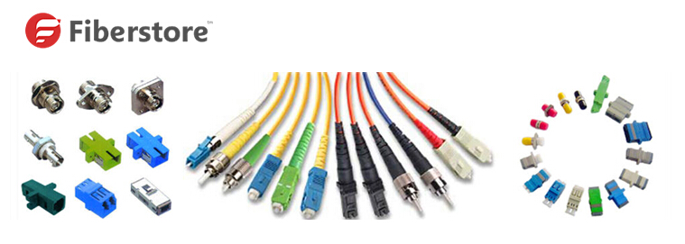
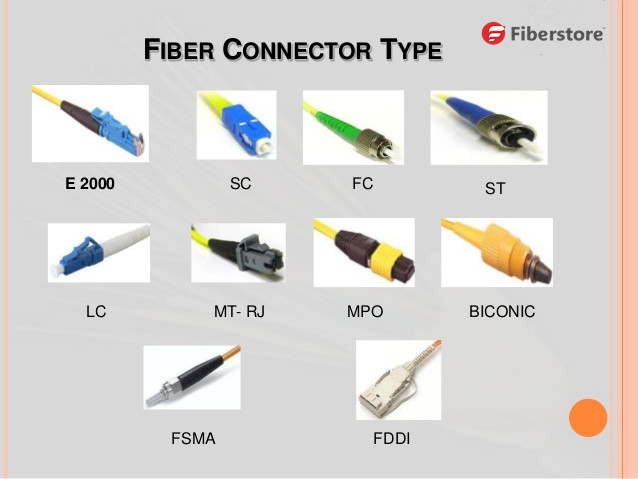
Connectors have evolved with the communications industry. Today’s users have a multitude of connectivity needs and the fiber industry has responded with innovative solutions. The most common connector in use today is the SC connector, the ST connector and the FC Fiber Connector. In addition the small form factor LC connector is used in high-density optical transmission products, and also for applications including fiber-to-the-home and dense wavelength division multiplexing where space is at a premium. Another connector gaining in popularity for use in high fiber count terminations is the MPO/MTP connector which can handle fiber counts as high as 96 using ribbonized fibers.

To understand fiber optic connectors one must understand both the mechanics and the optics involved. The ideal optical connector holds the fibers in perfect alignment, in three axes. This alignment must be maintained over hundreds or even thousands of connect-disconnect cycles to provide stable, repeatable attenuation characteristics.

The most important element of the connector plug is the ferrule, which provides the precise alignment and centering of the optical fiber. Ferrules can be made of ceramic, metal, glass or plastic. Zirconia ceramic ferrules or ceramic ferrules with metal inserts are most widely used, providing the best tolerances and durability. The most common ferrule sixes are the 2.5 mm used in the SC, ST, and the FC plugs. The 1.25 mm ferrule is used in the small form factor LC plug. For connectors designed for military and aerospace connectors the “termini” performs the same functions as the ferrule and are provided as both pin and sockets. Common connector types have SC connector, ST connector, FC connector, ect.


The body of the plug holds the ferrule, the coupling mechanism, and the boot. The body contains either a threaded, push-pull or bayonet coupling mechanism that mates the plug with the mating adaptor and also provides a keying function that allows the connector to mate in only one position. Strain relief of the cable is usually by a crimp sleeve or by adhesives which firmly secures the aramid yard in the cable to the plug body. At the rear of the plug body is the “boot” which functions as a bend radius limiter for the cable entering the plug body.

Another critical component is the mating adaptor, and its internal sleeve that aligns the two mating ferrules. Like the ferrule, sleeves are most often made from ceramic and can be either a split or solid construction. The alignment sleeve must precisely align the two precision ferrules by means of the ferrules outside diameters. This alignment must be done while providing a low-friction fit over a wide temperature range.

Over the years, fiber tolerances have greatly improved along with the mechanical tolerances of precision parts of the connectors.Early connectors suffered from poor alignment tolerances and mechanical stability problems due to loose fiber tole rances and mechanical tolerances of the connector design. The body and mating adapter also provide a keying function allowing the connector to mate in only one rotational position. This, combined with the tight tolerances of today’s optical fiber, ensures compliance with the Telcordia GR326 generic requirements repeatability standard of less than 2 dB connection loss over 500 mating cycles for single-mode fibers.

Today most lensed connectors work by expanding the beam exiting one fiber, then collimating the beam to the adjacent plug where a second lens is used to collect that light and re-direct it to the core of the second fiber. The main advantage of this approach is that the connector is less sensitive to alignment tolerances, so attenuation will remain more constant in the presence of vibration or temperature cycling. In addition the large area of the beam minimizes the impact of contaminants. The largest supplier of multi fiber expanded beam connectors are developed and manufactured by TE Connectivity and are provided in many variations for harsh environments such as mining, military, and aerospace applications.

Note: Fiber Optic Connector is an important components used in the fiber optic network. It is also the key part used in fiber optic patch cord and fiber optic pigtail. There are many kinds of fiber optic connectors. We supply one piece fiber optic connectors various types, including standard connectors and irregular types, epoxy types. we supply fiber optic types include: SC fiber optic connector, FC fiber optic connector, ST fiber optic connector, LC fiber optic connector, MU fiber optic connector, SC/APC fiber optic connector, FC/APC fiber optic connector,etc. Both Single mode fiber optic connector and multimode fiber optic connector available.

2015年6月24日星期三

LC Connector Design

The LC connector footprint is approximately half the size of an SC connector. The LC has a back shell designed to accommodate standard 1.6mm or 2.0mm diameter cable designs. The standard construction of the LC fiber connector consists of a spring loaded, 1.25mm diameter zirconia ceramic ferrule housed in a thermoplastic connector back shell.


The latch configuration depicted (Figure 1) is a front pivot design. The drawback with this design, especially in simplex (buffered) cross connect applications, is that the latch is open on the back and can easily snag on rack components, other connectors or conduit. In duplex applications it is less of a problem because the design of most duplexing clips incorporates a feature that allows the connector set to become “snagless”. Unfortunately, some of these designs necessitate the installation of the duplexing clip during the connector installation process. Installers performing behind the wall or behind the rack applications sometimes pull multiple channel pre-terminated cables through conduit and perform the duplexing at the outlet or rack port. The design of the “Rear Pivot Latch” LC Connector (Figure 2) is intrinsically snagless in simplex form (no clip is required to render the connector snagless) and minimizes risk in both applications mentioned above. The increased finger landing area on the rear pivot latch connector (Figure 2) also provides ergonomic latch access in high-density applications.
Another area of design differentiation among LC connectors is the protective cap included with the connector. Some LC designs include a cap that fits snuggly to the outside diameter of the ceramic ferrule nose of the connector (Figure 3). If an LC connector utilizing this type of cap is subject to a sudden impacting load to the front area of the connector that houses the ferrule, the possibility of breakage exists. The Rear Pivot Latch LC connector includes an innovative protective dust cap. The cap installs on the connector with an audible "click", and it does not directly bear on the sensitive ferrule end face (Figure 4).

In duplexing connectors together, a feature that enhances the ease of installation and minimizes TCO is a duplex clip that has the ability to be installed after connector termination. This type of clip snaps into place (Figure 5), providing the correct center-to-center spacing for the duplex application and the required A-B polarization markings. Some LC duplex designs require that these clips be mounted onto the connector pair in the course of fiber termination. If polarity changes are required, connectors must be re-terminated. Still, other LC duplex designs require tools to install or remove the clip. The design shown in Figure 5, requires no tools and can be easily installed and removed to facilitate connector changes.
The “Rear Pivot Latch” LC Connector design (Figure 6) incorporates design features that satisfy all of the design concerns mentioned earlier.
The snagless rear pivot latch assures easy installation by reducing the chance that the connector body will become snagged. The large, ergonomically shaped finger land area on the latch provides efficient moves, adds and changes. The duplexing clip can be installed after termination to assure rapid polarity changes. The unique protective dust cap with audible “click” serves to reduce the chance that the ceramic ferrule broken (during install or adds/changes). All of these things directly impact the TCO of the interconnect solution.
Fiberstore listened to our customers, and responded by delivering the next generation fiber optic LC Connector Solution for private and public networks. The LC Connector Solution was developed in response to customer needs for smaller and easier to use fiber optic connectivity. It simplifies moves, adds, and changes and saves you money. The LC Connector uses an improved version of the familiar, user friendly telephone plug, which provides a reassuring, audible click when engaged. The unique combination of small size and the click of connectivity makes the LC Connector the right choice for your network.
Key Features
    • Low insertion loss
    • Corrosion resistant body
    • Precision mechanical dimension
    • Meets Telecordia-GR-326-CORE
Fiberstore as the main professional fiber optic products manufacturer in china offer a various kinds of fiber cable connectors, FC Connectors, LC Connectors, SC Connectors, MPO Connectors and ST Connectors. You can buy fiber optic connection products on our store with your confidence. All of fiber optics supplies with high quality but low price.

2015年6月18日星期四

Popular Fiber Optic Connector Types You Must Know

Fiber optic connectors offer a disconnectable method for joining fibers to transmitters and receivers, other fibers and devices such as couplers and multiplexers. Most connectors are in the form of a cable-mount plug in which plugs mate with a feed-through receptacle that resembles a cylindrical coupling bushing. The inner diameter of the receptacle often has a split sleeve to provide a snug alignment of the mated plugs.
Because connector size is a primary factor in port density, cable connectors continue to get smaller. Most of this gain comes from the use of smaller ferrules. The newer MU and LC connectors use a 1.25 mm diameter ferrule, exactly half the size of a 2.5 mm diameter ferrule used in traditional FC, ST and SC connectors. Also, MT ferrule connectors are being combined in high-density arrays. Table 1 gives typical values for popular styles of connectors, grouped by ferrule size.
Popular Fiber Optic Connector Types
 
LC Connectors: The fully standardized LC connector utilizes a 1.25-mm ceramic ferrule and the versatile, pull-proof RJ-45 latching mechanism. Available in single-mode, multimode, simplex and duplex versions, they offer low insertion loss, low back reflectance and repeatable performance.
MU Connectors: The MU connector is one half the size of the standard SC connector, and is sometimes referred to as the mini-SC. Featuring a push-pull latching mechanism similar to the SC, the MU connector is easy to connect and disconnect. It provides a single point of disconnect in high-density applications, a feature often required by telecom operators.
SC Connectors: These emerged in the early 1990s as the general-purpose connectors of choice and are the recommended interfaces for premises cabling, ATM, Fibre Channel and low-cost FDDI. SC connectors use a 2.5 mm ferrule, push-pull locking mechanism and pull-proof design that prevents a slight pull on the cable from pulling the ferrule out of optical contact. Single connector plugs can be snapped together to form multiposition connectors.
ST Connectors: Originally developed by AT&T, they use quick-release bayonet couplings. A key ensures consistent, repeatable mating with the coupling bushing. They are available in a range of variations including ceramic, polymer or stainless steel ferrules and epoxy or epoxyless style termination. ST connectors remain the most widely and broadly used connector type.
FC Connectors: Used mainly by the telecommunications industry from which they derive, they use threaded couplings and 2.5 mm ferrules. Some variations of the connector use tunable keying to achieve the lowest loss. Tuning allows one ferrule to be rotated in relation to the other to minimize losses. The connector is keyed so that connectors will always mate in the tuned position.
FDDI-MIC Connectors and ESCON Connectors: Designed to meet the specifications of the ANSI X3.166 FDDI PMD (physical medium dependent) document, this duplex connector uses a side-latching mechanism and two 2.5 mm ferrules, as well as a fixed protective shroud to protect the ferrules. The connectors can be keyed according to fiber distributed data interface (FDDI) specifications, and also can be used for non-FDDI applications.
ESCON connectors, used in IBM ESCON channel interfaces, are similar to the FDDI-MIC connectors, but use retractable shrouds.
Plastic Fiber Connectors: These are available at low cost for fast termination to the cable, even at the expense of low loss. Most connectors require no epoxy, allow end finish to be achieved by trimming the fiber with a hot knife, and require little or no polishing.
Performance is in the 1 to 3 dB range. Many designs tend to be proprietary, although several standards have evolved using plastic fibers and connectors. Standardized applications include MIDI and digital audio, automotive and industrial automation. Many plastic fiber connectors incorporate LEDs and detectors directly as a means of reducing cost, simplifying the system and providing standardized parts.
MT-RJ Connectors: The MT-RJ is a two-fiber connector that resembles a standard telephone plug. The resemblance is intentional, as the connector is aimed at replacing the ST and SC types in wiring closets and at the desk. The connector fits in the same cutout as an RJ-45 jack, allowing fiber to be installed in network equipment, patch panels and wall plates without space penalties. The connector features a single, snagless latch. Rather than the typical fiber mating scheme that uses two plugs joined in a coupling adapter, the MT-RJ connector offers a true plug-to-receptacle mating technique. Plugs on the patch cable plug into a jack on the panel or faceplate. Fibers are terminated directly to the back of the jack with an epoxyless and no-polish termination.
High-Density Array Connectors: Multifiber array connectors such as LIGHTRAY MPX and MPO, and fiber-ribbon cable have been gaining in popularity (Figure 4). MT-style connectors, which use a small ferrule to hold 4, 8, 12 or 72+ fibers, provide the high-density interface required for high-bandwidth communications.
These connectors are used mainly in fiber arrays that replace the rat’s nest of coaxial cable associated with mainframe computers. They offer a neat, compact and orderly method to connect equipment.These arrays are typically fanned out with jumper cables terminated in standard connectors, such as an ESCON duplex connector, to form the interface to the system equipment.

Conclusion
Fiber optic connectors are available in a wide range of configurations. The choice of connector typically depends on the applications.
Connectors offer low insertion losses well within the reasonable demands of applications. Application speed, the required interface and special environmental or mechanical requirements may narrow the selection, but overall connector selection should be neither difficult nor tricky.

2015年6月17日星期三

50 versus 62.5 Micron Multimode Fiber

Multimode fiber systems continue to provide the most cost-effective cabling solution for data centers, local area networks (LANs), and other enterprise applications. Compared to singlemode fiber, multimode systems offer significantly lower costs for transceivers, connectors, and connector installation while meeting and exceeding the bandwidth and reliability requirements of the most demanding networks.
If you are designing a new short-reach installation, you will probably choose laser-optimized 50-micron (µm) OM3 or OM4 multimode fiber. These fibers preserve the systems-cost benefits over singlemode fiber by using low-cost 850-nm vertical-cavity surface-emitting laser (VCSEL) technology, are capable of 10-Mbit/sec through 10-Gbit/sec operation, and will support upcoming 40- and 100-Gbit/sec transmission speeds.
But if you are upgrading an existing system, many of which have 62.5-µm multimode already installed, should you stick with 62.5-µm? Or can you go with the higher performance of 50-µm OM3 or OM4 fiber? This article highlights the things you must consider when upgrading an existing 62.5-µm system.
multimode fiber
Before discussing the 62.5-µm and 50-µm fiber, we first display you 62.5-µm and 50-µm fiber patch cable from Fiberstore.
Multimode 62.5-µm (OM1) Optical Fiber Patch Cords
Multimode optical fiber patch cords can be used as cross-connect jumpers, equipment and work area cords. All Fiberstore optical fiber patch cords are manufactured using OFNR riser grade cable and are 100% factory tested for insertion and return loss to ensure transmission performance per ANSI/TIA-568-C.3 standard specifications. Multimode 62.5-µm patch cords terminated with ST, SC, and LC connectors (uniform and hybrid versions) are available in duplex and simplex designs. They are LC SC 62.5/125 multimode fiber patch cable, LC ST simplex multimode fiber patch cable, SC ST duplex multimode fiber patch cable, ect.
Features
  • LC, FC, SC, ST, MU, MTRJ, E2000, SMA connector
  • Fiber Types: Simplex, Duplex
  • Micron: 62.5/125um
  • Complete with Lucent Technologies aqua jacket Bandwidth transmitting rates up to 10 gigabits
  • All of our fiber optic patch cables feature the high degree connectors 100% optically tested to ensure high performance
  • Color: Orange
  • Fiber class: OM1
Multimode 50-µm Optical Fiber Patch Cords
Fiberstore 50/125 Multimode Fiber Optic patch cables feature machine polished ceramic ferrules in a variety of connector terminated including FC, LC, MT-RJ, MU, SC, and ST. 50-µm fiber has OM2, OM3, OM4. Common 50-um fiber patch cable have LC-MTRJ 50/125 Multimode Fiber Patch Cords, LC SC 50/125 Multimode Fiber Patch Cords, ST SC 50/125 Multimode Fiber Patch Cords, ect. 50-Micron Multimode Fiber (MMF) is rapidly gaining in popularity due to its expanded bandwidth potential over traditional multimode fiber runs. Supporting nearly 3X the bandwidth over twice the distance, 50/125 fiber is recommended for all new premise applications including intra-building connections. When fiber optic band cables are needed that offer more bandwidth than traditional options, this product is one that delivers.
Why two fiber sizes?
The numbers under discussion—50-µm and 62.5-µm—refer to the diameter of the fiber’s core, through which light signals are transmitted. The first optical fibers, deployed in the 1970s for both short- and long-reach applications, were 50-µm multimode fibers. In the early 1980s, singlemode fiber replaced 50-µm fiber in longer-distance installations. However, 50-µm multimode continued to be more cost-effective for short-reach interconnects, such as building and campus backbones, up to 2,000-meter distances.
But as data rates increased, 50-µm fiber could not support 10-Mbit/sec rates over the 2-kilometer distances required by some campus installations. Not enough power could be coupled from the light-emitting diode (LED) sources in use at that time into the 50-µm core to support these link distances.
62.5-µm multimode fiber was introduced in 1985 to solve this problem. It could capture more light from a LED in its larger core, and 2-km campus links operating at 10 Mbits/sec were easily supported. Also, the larger-core fiber was easier to cable and connectorize. It became the most commonly used fiber for short-reach enterprise applications in North America.
Today, as data rates surpass 10-Gbits/sec and lasers have replaced LEDs, 62.5-µm fiber has reached its performance limit. 50-µm fiber offers as much as 10 times the bandwidth of the 62.5-µm fiber. What’s more, improvements in technology have made 50-µm fiber easier to use.
Which technology should I choose?
Given its superior technical characteristics for high-speed links, 50μm fiber is the clear choice for new multimode fiber links in most circumstances. Standards organizations including IEEE, INCITS, InfiniBand, OIF, TIA, IEC and ITU-T all specify laser-optimized 50μm fiber for new high-speed network installations. OM3-grade, high-bandwidth 50/125-micron fiber cable increases the flexibility of network designs and achieves data transfer rates up to 10 Gbps at the lowest available cost. Multimode 50μm fiber is the medium of the future, with 62.5μm fiber being supported chiefly for legacy purposes. However, the majority of the fiber deployed in the world today is 62.5μm, so backward compatibility is an important concern.
Assuming you already have 62.5μm fiber in your plant, should you stick with 62.5μm, or migrate to 50μm? As a first consideration, industry standards and leading media and equipment manufacturers recommend that you should not mix different types of fiber in a single link. If you have a 62.5μm run in the wall, that link should use all 62.5μm patch cables and equipment, including 62.5μm Net Optics Taps. However, extensive testing by Corning has shown that the signal loss from joining dissimilar fiber segments, when necessary, is small.
On the other hand, there are no technical drawbacks to using different fiber types in separate network links, as long as the ports at both ends of the link are compatible with the cable. Moreover, there is little if any cost difference between 62.5μm and a 50μm products in today’s market. Therefore, installing 50μm fiber for new network links is a good investment for future growth, even if your current plant has mostly 62.5μm fiber.
With the demand for network capacity increasing daily, upgrades must be planned with an eye to the future. Installing 50μm multimode fiber today brings immediate benefits of longer cable reach and improved light loss budget margins, and prepares the network for future upgrades. If you haven’t started already, it’s time to begin phasing out 62.5μm fiber and moving into the world 50μm for higher performance and better returns on your network investments.
About Fiberstore
Fiberstore provides both Singlemode and Multimode patch cables (including OM1, OM2, 10G OM3 and 10G OM4) that are available in Duplex and Simplex, as well as Plenum-rated. In addition, all the cables can be customized in optional lengths. On the other hand, Fiberstore provides a wide range options of plenum fiber patch cable which include SC, FC, LC, ST, MU, MTRJ, E2000, MTP etc, both single mode and multimode plenum rated fiber optic cable assemblies. Additionally, custom lengths, connector combinations and polishes are available. Our each fiber optic patch cable is individually tested and certified to be within acceptable optical insertion loss limits for guaranteed compatibility and 100% reliability, and is backed by our lifetime warranty.
This article comes from: http://www.fiber-patch-cords.com/blog/a/85/50-versus-62.5-Micron-Multimode-Fiber

2015年6月16日星期二

LC Connector in Fiber Management and Transceivers

fiber optic connector
Fiber Optic Connector is an important components used in the fiber optic network. It is also the key part used in fiber optic patch cord and fiber optic pigtail. There are many kinds of fiber optic connectors.we supply one piece fiber optic connectors various types, including standard connectors and irregular types, epoxy types. we supply fiber optic types include: SC fiber optic connector, FC fiber optic connector, ST fiber optic connector, LC fiber optic connector, MU fiber optic connector, SC/APC fiber optic connector, FC/APC fiber optic connector, etc. Both Single mode fiber optic connector and multimode fiber optic connector available. Today we mainy introduce the LC connector in fiber management.

LC patch cables management 

LC connector is a small form-factor (SFF) fiber optic connector. It uses a 1.25 mm ferrule, half the size of the ST. Otherwise, it is a standard ceramic ferrule connector. The LC has good performance and is highly favored for small form factor, high-density fiber optic connectivity with simplex, duplex, single-mode and multi-mode options. It has been gaining the preference of equipment manufacturers because of its compact size and performance.

The LC connector system, standardized as TIA/EIA FOCIS-10, was designed specifically to address the needs of increasing network interconnect density. In the past, fiber management systems (for D4, ST, FC and Biconic), have required twice as many individual connectors as copper systems, hence, crowding racks and closets with additional patch bays, management hardware and line terminating electronics. SFF connectors have either a unitary body design (FJ and MT-RJ) or a provision for clipping simplex connectors together to form a single SFF end (LC). The LC connector provides the potential for twice the interconnect density in closets and racks when compared to a SC connector. Although, there is a point at which additional density cannot be utilized because of the difficulty in fiber routing inordinately large cable counts. Also at issue in these higher density racks, is the problem of disturbing adjacent circuits in MACs. Most important in fiber management, is the decreased footprint of the LC on electronics (hubs, switches, etc.) for fiber transceivers.

transceiver-and-lc-patch-cable 

In the emerging SFF connector landscape, the LC connector is clearly the leader in performance as well as installed base. Since the LC connector has been licensed widely and is now offered by most major cabling system vendors (including some early proponents of MT-RJ), the exact number of LC connectors shipped is difficult to ascertain. However, at least one vendor has shipped over 24 million LC connectors, with a mix of approximately 60% multi-mode and 40% single-mode. The MT-RJ connector places a distant second in both performance and installed base. The multi-mode version has found some support with a few large transceiver vendors and LAN equipment manufacturers, particularly for the less demanding 100BASE-FX interfaces. However, the LC connector is quickly becoming the preferred transceiver connector for high bit rate applications (1 Gb/s and above) due to its numerous advantages for transceiver design. More transceiver manufacturers support the LC interface than any other SFF connector, and LC transceivers are available from numerous sources for applications ranging from 10 Mb/s to 10 Gb/s.

The specific characteristics of the LC connector, including wide fiber spacing, better fiber alignment, precision mating, ease of connector cleaning, and simplex/duplex configuration, combine to produce overall superior performance for both factory-terminated and field installed connectors. This is apparent that the LC connector is the best choice for a cabling infrastructure. Meanwhile, for fiber management and transceivers, there is no doubt that LC connector is an ideal solution.

Fiberstore as the main professional fiber optic products manufacturer in china offer a various kinds of fiber cable connectors, FC Connectors, LC Connectors, SC Connectors, MPO Connectors and ST Connectors. Each fiber optic connector family has supporting performance data based on accepted industry testing procedures specified by the most current version of ANSI/TIA/EIA-455B. You can buy fiber optic connection products on our store with your confidence. All of fiber optics supplies with high quality but low price.

2015年6月14日星期日

In-Depth Understanding of Fiber Optic Patch Cable

LC LC patch cable
Fiber optic patch cable can be one of the most commonly used components in fiber optic networks, since the increasing popularity of fiber optic cable. Fiber optic patch cable serves as a bridge during the information transferring through fiber optic cable. This post aims to help you get a better understanding of fiber optic patch cable and propose solutions by Fiberstore.
What is Exactly Fiber Optic Patch Cable?
Fiber optic patch cable, often called fiber optic patch cord or fiber jumper cable, is a fiber optic cable capped at either end with connector that allows it to be rapidly and conveniently connected to CATV (Cable Television) an optical switch or other telecommunication equipment. Its thick layer of protection is used to connect the optical transmitter, receiver, and the terminal box. This is known as "interconnect-style cabling".
Applications
Fiber optic patch cables are used for wide applications, such as, connections to CATV, telecommunication networks, computer fiber networks and fiber test equipment, including communication rooms, FTTH (Fiber to The Home), LAN (Local Area Network), FOS (fiber optic sensor), Fiber Optic Communication System, optical fiber connected and transmitted equipment, defense combat readiness, etc.
Types of Fiber Optic Patch Cables
Fiber optic patch cables can be divided into different types based on varies criteria.
In terms of fiber cable mode, fiber optic patch cables can be described in single-mode and multi-mode fiber patch cables. Single-mode fiber optic patch cables use 9/125 micron bulk single-mode fiber cable and single-mode fiber optic connectors at both ends. Single-mode fiber optic cable jacket color is usually yellow. While multi-mode fiber optic patch cables use 62.5/125 micron or 50/125 micron bulk multi-mode fiber cable and terminated with multi-mode fiber optic connectors at both ends. Multi-mode fiber optic cable jacket color is usually orange.
From fiber cable structure aspect, fiber optic patch cables can be classified into simplex fiber optic patch cables and duplex fiber optic patch cables. Simplex fiber patch cable has one fiber and one connector on each end. Duplex fiber patch cable has two fibers and two connectors on each end. Each fiber uses "A" or "B" or different colored connector boots to mark polarity.
By connector construction standard, fiber optic patch cables include FC, SC, ST, LC, MTRJ, MPO, MU, SMA, FDDI, E2000, DIN4, and D4. Cables are classified by the connectors on either end of the cable; some of the most common cable configurations include FC-FC, FC-SC, FC-LC, LC ST fiber cable, SC-SC, and SC-ST.
Fiberstore Solution
Fiber optic patch cables with high quality are characterized by low insertion loss, high return loss, good repeatability, good interchange, excellent environmental adaptability. Fiberstore can supply various types of fiber patch cables, including LC to SC fiber patch cable and LC-LC Simplex 9/125 Single-mode Fiber Patch Cable. With LC to LC termination, complete with Lucent Technologies aqua jacket, bandwidth transmitting rates up to 10 gigabits, cost-effective solution that specifically designed for gigabit Ethernet applications, these fiber optic patch cables can provide 100% optically tested to ensure high performance. Fiberstore provides high standard and trusted quality, accurate return purchase and barter service, professional maintenance service to satisfy your requirements.

2015年6月12日星期五

Share Some Basic Knowledge About Fiber Optic Connectors

Fiber optic adapter

Remember that connectors are used as terminating fixtures for temporary non-fixed joints. As such, they are made to be plugged in and disconnected hundreds and possibly thousands of times. Since no one connector is ideal for every possible situation, a wide variety of connector styles and types have been developed over the short life of fiber communications. We can classify connectors by assigning them into five major categories:

1, Resilient ferrule 2. Rigid ferrule 3. Grooved plate hybrids 4. Expanded beam 5. Rotary
Of these types the rigid ferrule is by far the most common. Rigid ferrule types include the popular ST (compatible), FC, and SC, which use a single 2.5 millimeter cylindrical ferrule for fiber alignment. Other simplex connectors housing a single fiber, but no longer in common use today, include the SMA (905 and 906), D4, and the Biconic.

Duplex connectors contain two fibers allowing for a single connector body for both transmit and receive fibers. These connectors have come to the fore in recent years and are expected to gain popularity in the LAN arena. LAN hard ware manufacturers have already adopted these connectors since they offer a much smaller size, allowing more links per panel space on network equipment.

Early examples of duplex connectors include the FDDI and ESCON. These connectors are rather large and cumbersome. Newer duplex connectors are designed to fit in the same work area outlet space as a standard RJ45 telephone jack and include the MT-RJ, Opti-Jack, and Volition connectors. These are commonly referred to as small form factor (SFF) connectors.

Although some SFF connectors are duplex designs, several others are miniature simplex connectors that are similar in design to the SC. The LC, LX-5, and MTRJ connector use smaller 1.25-millimeter ferrules and miniature bodies to allow twice the panel density of the earlier simplex connector designs.

The end of an optical connector (Figure 6-4) can be either polished flat or with a PC finish, a slightly rounded, domed end to create a “physical contact,” hence the PC designation. Physical contact of the fibers reduces the back reflection caused by air between the fiber ends. Some singlemode connectors may also have an “angled PC” (APC) finish. The ends are angled at 8 degrees to minimize back reflections at the point of connection. These connectors cannot be mated with the normal flat or domed polish types (Figure 6-4).

Although few, if any, of the original designs were compatible, nowadays compatibility exists between the same types from different manufacturers (i.e., ST or SC designs), thanks to marketplace pressures and standards committees. Although not compatible with all other connector styles, most ferrules are 2.5 millimeters and will loose fit for temporary testing purposes. For example, by lightly inserting the ferrule of an ST into an FC coupler, a “quick-and-dirty” test can be made for continuity. Hybrid adapters to allow coupling of different types of connectors are generally available as either sleeve connectors or patch cords. Although no single connector is best for every application, Table 6-1 lists the currently popular connectors found in many different types for various applications.

Choosing a Fiber Connector

fiber optic connector

With all of the myriad selections of connector types, styles, and physical characteristics available on the market, choosing the specific connector for your job is often a mystifying task. One important criterion is connector performance. When selecting a connector, comparisons of performance are generally based on:

* Insertion loss, usually 0.10 to 1.0 dB per connection * Return loss (back reflection) varies from –20 (air gap like a SMA) to –60dB (the best APC angle polished connectors) * Repeatability of connection, usually specified at thousands of times
Your choice of fiber connector also may depend on whether you are mounting it onto singlemode or multimode fiber. Since singlemode connectors have a much tighter tolerance than multimode connectors, they may be used on either type of fiber. However the reverse is not true, that is, one may not use multimode connectors on single mode fiber because the loose tolerance will cause high loss with the very small singlemode core size. Generally multimode connectors are fitted onto multimode fibers because they are less precise and cost about one-half to one-third the cost of single mode connectors.

The accessibility of the fiber to casual users may cause you to anticipate rough handling. In this case, gripping strength of the connector on the cable becomes important to avoid pullouts by users. Gripping points of the connector may include the fiber itself, the primary plastic buffer coating (tight buffer), the loose tube buffer, the cable strength members (Kevlar), and/or the cable jacket itself.

Another reason for choosing a particular type of connector is the type of equipment already purchased or currently in use. If, for instance, you are adding to an existing system already equipped with ST fiber connector, you should continue to use ST connectors to ensure compatibility systemwide. If you are using previously purchased electronics with Biconic connectors installed, then that will be your choice, unless, of course, you want to change all of the connections on the patch panels and electronics.

Finally, your choice may be influenced by industry standards or new developments in the marketplace. The Electronic Industries Alliance/Telecommunications Industry Association (EIA/TIA) standards for premises cabling calls for the SC connector, although they are considering the new SFF connectors. Many of the newer connectors offer the promise of lower cost or higher performance, which can also influence the decision.