2014年5月29日星期四

One of Most Major applications of Optic Fiber—FFTH

FTTH (Fiber To The Home), it is Fiber Optic Patch Cables directly to the home. Specifically, FTTH optical network means (ONU) installed in the home or business user of the user, the optical access network is a series of optical access the user application type except FTTD (fiber to the desktop) closest outside. FTTH technology is characterized by significant not only provides greater bandwidth, but also enhanced network data format, speed, wavelength and protocol transparency, relaxed on the environmental conditions and power requirements, simplifies maintenance and installation.

FTTH advantage

1.FTTH is a passive network, from the central office to the user, fiber optic coupler, fiber optic passive components accounted for most of the equipment, it can be done in the middle basically passive
2.It is relatively wide bandwidth. Large-scale use is in line with the way long distance carriers.
3.It is a direct bearing on the fiber business, so there is nothing complex issues.
4.Because of its relatively wide bandwidth, support for the agreement is more flexible.
5.With the development of technology, including point to point, 1.25G and FTTH way have developed a relatively complete function.

The optical fiber directly to the user's home, its bandwidth, wavelength and transmission technology types are no restrictions for the introduction of new services, it is the ideal business transparent network, and it is aslo the ultimate way to access network development. Although the development of mobile communications at an alarming rate, but because of limited bandwidth, terminal volume can not be too large, the display screen is limited and other factors, it is still pursuing a fixed terminal performance, which is hoped to achieve FTTH. Fiber to the home's charm lies in its great bandwidth, it is the best solution to solve from the Internet backbone to the user's desktop bottlenecks.

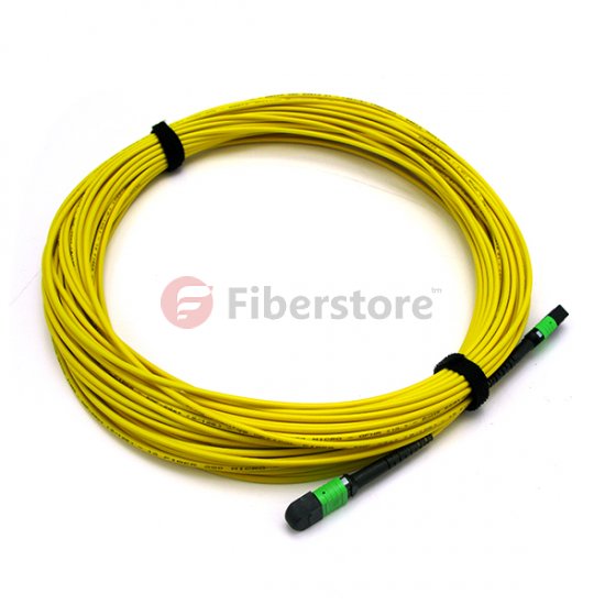
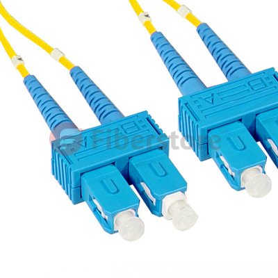
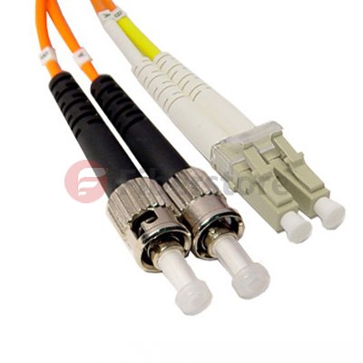
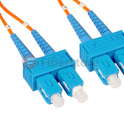
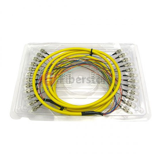
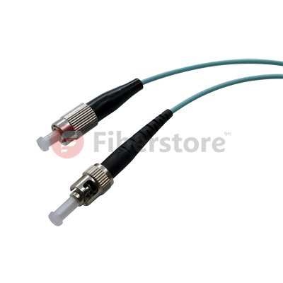
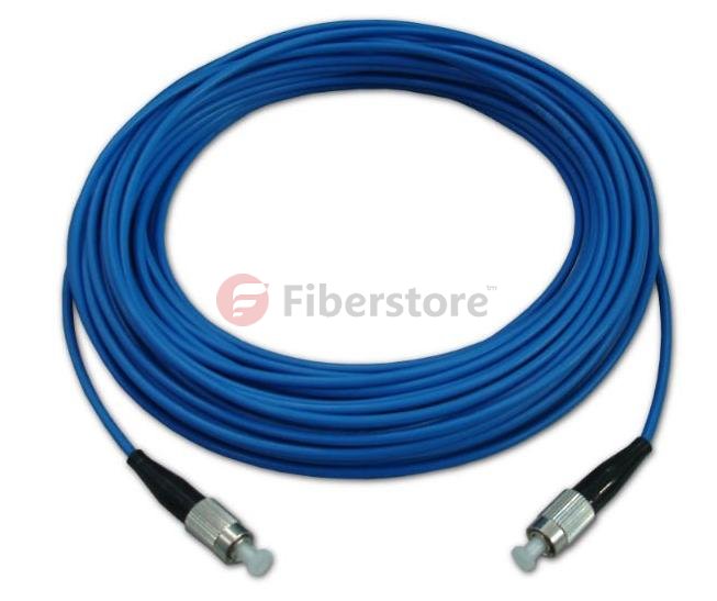
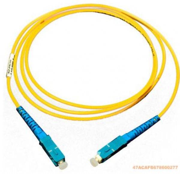
The related products about optical fiber, FC/UPC to FC/UPC 4 Fibers SM 9/125 Single mode Fiber Patch Cable
  Single Mode Fiber Patch Cable  
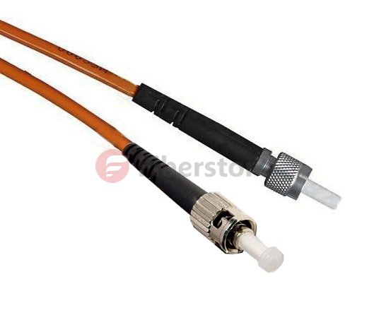
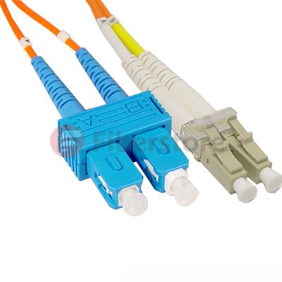
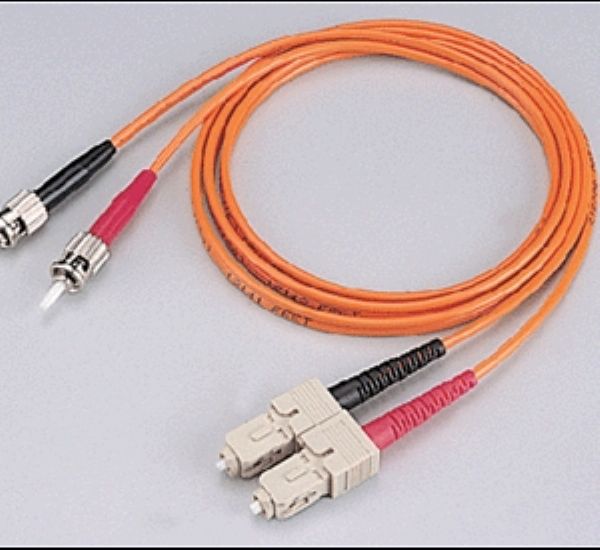
FC-FC 6 Fibers OM1 62.5/125 Multimode Fiber Patch Cable Multimode Fiber Patch Cable
 With the upgrading of technology, greatly reduces the cost of fiber to the home, it will soon be reduced considerably with DSL and HFC networks, which makes it possible for practical FTTH. In China, FTTH is also imperative. From 2011, in China from coastal cities to inland cities, from east to west, opened the curtain FTTH construction. You can say that FTTH is a highlight of optical fiber communication. Accompanied by a corresponding technologies mature and practical, cost closer to ordinary families can afford to reduce the level of FTTH trend is unstoppable.

Furthermore, FTTH technology is still used to solve the "last mile" problem of the information superhighway. FTTH + Ethernet over ADSL (ADSL dial-up time will be established at the highest theoretical 8Mbps download bandwidth, this bandwidth is never changed, but in fact, because the noise detection mechanism ADSL line situation is not good, if it is clearly beginning to establish a connection not reach the theoretical value, may finally be 5Mbps, this bandwidth is also not change.) and ISDN (European popular form of telephone network) transmission speed is much faster.

FTTH has been considered a rising star ultimate ideal access networks, but also broadband development. Because it can meet the diverse needs of various users. Like high-speed communications, home shopping, high-definition television, video on demand and more. The copper wire is the reluctance of the business, it is easy for FTTH. One can imagine, FTTH is to realize telephone, cable TV and Internet "triple play" the best choice.

2014年5月27日星期二

10G Ethernet Transmission MPO System Scheme

June 2002, IEEE802.3ae Task Force issued a series of fiber-based Gigabit Ethernet standard, commonly used in LAN 10GBase-SR/SW as example, 10GBase-SR/SW using serial transmission technology, that is, each core optical fiber only send or receive signals, so to achieve 10Gbps transmission requires at least two-core optical fiber.

MPO fiber optic deployment system has two solutions, one is to use the program with MPO module box, because MPO module box is with metal needles, therefore MPO trunk cables do not need to distinguish whether with a metal pin (Pin), most users tend to use MPO module case scenario; another option is to use MPO coupler, such programs must differentiate between MPO trunk cables with metal needles and without metal pin, the other two ends need to convert Fiber Jumper, so this program is rarely adoption.

According ANSI/TIA-568-C.3 standards are divided into the following two types of duplex Fiber jumpers:

Standard: (A-B) MPO Fiber Non-Standard: (A-A) MPO According ANSI/TIA-568-C.3 standard, MPO coupler is divided into Type A, Type B two types: MPO Fiber Connector   MPO Fiber Optic MPO fiber optic system according to the MPO trunk cables, MPO module boxes and jumpers of different types have different combinations of programs, mainly A, B, C three kinds of channel combination scheme

Method A: Using straight-through (Type A) of MPO trunk cables, Fiber Jumpers must be used at both ends of different models, Scenario A increases the complexity of the orders, it is not recommended to use programs A.

Method B: A fully cross (Type B) of MPO trunk cables, MPO module box must use two different types (Key Up-Key Up) and (Key Down-Key Down), another plan B does not support the ramp octave end face (singlemode fiber, so most manufacturers do not recommend using program B.

Method C: Using lines cross (Type C) of MPO trunk cables, MPO consistent at both ends of the module box (Type A) and standard jumpers, so Option C is the solution of choice for 10G Ethernet recommended.

There are some related MPO products from fiberstore, you can see to know more about MPO Fiber.

12 Fibers, Single-Mode, 12 Standard MPO Fiber Cable,3.0mm LSZH MPO Trunk Cable

FiberStore offer singlemode and multimode (OM1, OM2, 10G OM3, 10G OM4) MPO/MTP Cable. Singlemode MPO MTP Fiber cable is primarily used for applications involving extensive distances, 10G Mpo Cassettes provide 10 gigabit data transfer speeds in high bandwidth applications and they are 5 times faster than standard 50um fiber cable. Work with both VCSEL laser and LED sources. The meanwhile, we also provide 40G/100G MPO/MTP trunk cable.

2014年5月26日星期一

The Advantages And Disadvantages of Multimode And Single-mode Fiber

1. The Development of Optical Fiber

1.1 Development of Single-mode Fiber

The late 1970s, people tried to use the successful development of long-life semiconductor laser light source to replace the light tube, in order to get longer communication distance and greater communication capacity. However, the laser pattern noise occurs in the multi-mode transmission fiber. To overcome pattern noise, in 1980 successfully developed the zero dispersion point at 1.31m single-mode fiber (non-dispersion shifted single-mode fiber). The International Telecommunication Union (ITU-T) recommended that such a single-mode fiber is defined as G.652 fiber. Because the design of a single mode fiber is only thinking of a transmission mode, so the pattern noise in the transmission multimode fiber occurred does not occur. Thus, the mid-1980s, by the laser light source and composition of the 140sMbit G.652 Fiber Optic Patch Cables communication systems [2], which, following distance and transmission capacity far exceeds the coaxial cable so that the optical fiber communication gradually replace the use of copper to become the the main means of communication in telecommunications industry.

1.2 Development of Multi-mode Fiber

Thinking of optical fiber communication by Chinese-American Kao paper published in 1966 , " optical frequency dielectric fiber surface waveguides " made of quartz glass optical signal transmission fiber ( referred to as optical fiber ) to communicate. In 1970, the British telecommunications, Bell Labs and Corning Glass Company jointly developed the world's first root attenuation coefficient 20kmdB Multimode Fiber Cables[ 3 ]. It should be noted that the multi -mode fiber as the optical transmission medium of the semiconductor laser and a long life as a prelude optical fiber common carrier communication research. Expand and increase the transmission speed of the optical fiber communication transmission capacity, transmission distance is extended and the fiber attenuation is closely related to dispersion and nonlinear effects. Innovation process is that the people of fiber varieties of fiber attenuation, chromatic dispersion , nonlinear effects in optical fiber communication systems and other performance plays an important role in the recognition process. 1976 Bell Labs in the United States between Atlanta to Washington establish the world's first practical optical fiber communication systems,the transmission speed of 45sMbit, uses a multi-mode fiber . Multimode fiber always is trying to reduce the attenuation and mode dispersion, and further improve the transmission bandwidth of optical fiber as the research center. In recent years, studies have multimode fiber mutagenicity progress, fiber transmission bandwidth has been greatly improved.

2. Principle of Multimode Fiber and Single-mode Communication

Optical fiber communication is the use of light as a carrier to transmit information, and optical fiber as a transmission medium to achieve information transmission, one of the latest communications technology achieve the purpose of communication. Therefore, the principle of the optical fiber and the transmission of information studies is important.

First, optical fibers transmit information use the principle of total reflection of light, i.e., when the light from the optical dense medium (higher refractive index medium) optically thinner medium intake, the refraction angle will be greater than the incident angle, when the incident angle to a certain degree, the angle of refraction of the incident angle of 90 °of this case referred to the total reflection angle. When the angle of incidence continues to increase, will not happen this time refraction, reflection and safety of all incident light is reflected Theorem. This phenomenon is a reflection. To achieve total internal reflection optical fiber to satisfy two conditions: Light must be incident light from the optically denser medium to dense medium; Angle of incidence must be greater than the critical angle. Thus, a practical optical fiber essentially consists of three parts, namely, a high refractive index of the core portion and the refractive index of the lower cladding layer and the outer coating layer.

There are many classification of Fiber Optic Patch Cables, but there is a very important classification, according to the number of conduction-mode fiber to classify, so-called "model" refers to a certain angular velocity of a beam of light into the fiber. Only one mode of conducting could be single-mode fiber, the fiber can be transmitted to a plurality of mold for hundreds of patterns is called a multi-mode fiber. It is possible to determine the number of transmission modes, an important structural parameter is the normalized frequency of the fiber, generally denoted by V, defined as:

Fiber optic calbe

2.1 Multi-mode Optical FiberThe number of fiber conduction mode with its normalized frequency, the total number of conduction mode similar to:

Multimode Optical Fiber

Wherein, V is the normalized frequency of the fiber, αis the fiber refractive index profile exponential. For example, the total number of parabolic fiber α=2, the conduction mode is:

Fiber optic cables


2.2 Single-mode Optical FiberOnly one mode fiber transmission is called multimode fiber, Single Mode Fiber Cable can transmit the fundamental mode (lowest-order mode), there is no difference between the mode delay. Therefore, single-mode fiber refractive index α profile exponential impact on its far less bandwidth multimode fiber is generally used large step-index profile.

Singlemode Fiber optic cables

2014年5月25日星期日

Key Technologies And Development of Multi-mode Optical Fiber

Corning and Lucent and other large companies proposed a "new generation of multi-mode fiber" concept to the international standardization bodies. A new generation of Multimode Fiber Patch Cable; standards drafted by the International Organization for Standardization / International Electrotechnical Commission (ISO / IEC) and the Telecommunications Industry Alliance (TIA-TR42). As a new generation of multi-mode fiber transmission medium 10Gb / s Ethernet, be included in IEEE 10Git / s Ethernet standard. This article will briefly describe the new generation of multi-mode fiber critical technical information.

1.1

The Typle of New Generation of Multimode fiber

The new generation of Multimode Fiber Cable is 50/125μm, graded-index multimode fiber distribution. The number of this transmission mode Fiber Optic Cables is approximately 62.5μm multimode fiber transmission mode 1/2.5. This can effectively reduce the dispersion of the multimode fiber mode, increase the bandwidth. For 850nm wavelength, 50/125μm Multimode fiber bandwidth is 500MHz.km. Recent experiments confirmed: the use of 850nm vertical cavity surface emitting laser (VCSEL) as a light source in the 1Gb / s rate, 50μm multimode fiber core diameter standard error can be no transfer 1750m, 50μm core diameter multimode fiber can be a new generation of error-free transmission 2000m. In the 10Gb / s down, 50μm core diameter multimode fiber can transmit a new generation of 600m. A new generation of multi-mode fiber is mainly used to support high-speed Ethernet (Ethernet), Fibre Channel (FC) and fiber optic interconnection (OIF). Meanwhile at 10Gbit / s system can transmit 600m, so that it can be used for building backbone and campus backbone extraordinary distance from the middle. In the data center design, within a distance of 100m to support higher speed (40G and 100Gbits / s? Ethernet, 16G and 32Gbits / s Fibre Channel) data transmission requirements.

The related products about New Generation Multimode fiber, SMA905-ST Duplex 50/125 Dia2.5mm OM2 Multimode Fiber Patch Cable from fiberstore.com, the products picture is below:

OM2 Multimode Fiber
The SMA-905 fiber optic patch cord, also known as FSMA connector, was one of the First fiber optic interconnect system that gained industry wide acceptance.SMA905 fiber patch cords make use of threaded connections and is still widely used for military, industrial, medical and Surgical applications and laser systems because of their low cost multimode coupling. It features simple termination and Assembly, and is TIA and IEC compliant. SMA 905 multimode connectors are available with stainless alloy or stainless steel ferrules.

1.2 A New Generation of Multi-mode Fiber Source

Traditional multimode fiber networks use light-emitting diode (LED) as light source . In low-speed network, which is an economically rational choice. However, LED is spontaneous emission light, the radiation -emitting laser is excited , the carrier lifetime is longer the former than the latter, and thus the LED modulation rate is limited , and not more than gigabit networks. Further, LED compared with a laser, the beam divergence angle, wide spectral width . After injection of multimode fiber , excite more high-order mode, the introduction of more wavelength components, so that the fiber bandwidth decreases . Fortunately 850nm vertical cavity surface emitting laser (VCSEL) not only has the advantage of these lasers, but aslo the price is basically the same with the LED. Other advantages of VCSEL are: low threshold current, may not be enlarged, driven directly by logic gates at 10Gb / s rate, get a few milliwatts of output power; emission wavelength of 850nm which does not apply to the standard single-mode fiber just for multimode fiber . At this wavelength, an inexpensive silicon detectors can be used and have a good frequency response; VCSEL another remarkable advantage is that the manufacturing process can be easily controlled distribution of the emitted light power , which is very advantageous for improving the bandwidth of MMF. It is because of these advantages, the new generation of multimode fiber standard will use 850nm VCSEL light source.

1.3

The Bandwidth Distance of New Generation Multimode Optical Fiber
By comparing the above- described laser and LED , the use of multimode fiber laser light source, the transmission bandwidth should be greatly improved. However, experimental results show that simply make the bandwidth of a laser instead of LED light source, system is not only reduced but increased. IEEE Expert Group found through research, the bandwidth of multimode fiber and the optical fiber or the injection molding state of a power distribution. The preform fabrication process, the refractive index of the fiber axis prone to depression. Done before light source LED, is overfilled launch (OFL-Over Filled Launch), all of the fiber mode ( hundreds ) are excited to bring their own part of each module power. The refractive index of the fiber center delay characteristic distortion affects only a small number of models, the relatively limited impact on the modal bandwidth of the fiber. The measured multimode fiber bandwidth for the use of LED light source system is correct. However, when a laser light source, a laser beam spot is only a few microns, the divergence angle is smaller than the LED, so that only a small number of modes excited in the center of the fiber transmission, each mode carries a large part of the power, the refractive index of the fiber center distortion affect a small number of patterns of delay characteristics, so that decreased multimode fiber bandwidth. So it can not be measured with a laser light source for multimode fiber OFL bandwidth of conventional methods.
Today a new generation of multi-mode fiber main measurement bandwidth limit die by injection method (RML-Restricted Mode Launch). In this way the measured bandwidth is called " laser -bandwidth " or " modal bandwidth limit ", previously done with the LED light source measured bandwidth is called "OFL bandwidth is ." Both represent the bandwidth of multimode fiber laser and LED light source with a time of injection. August 5, 2009, TIA Standards Committee released a new generation of bandwidth distance product standard multimode fiber , 850nm laser distance -bandwidth product of 470MHz.km, 850nm OFL bandwidth of distance product of 350MHz.km, 1300nm OFL bandwidth of distance plot to 500MHz.km. Incidentally, the bandwidth from the product of the above-described generation of the multi-mode fiber is only 3dB corresponding baseband bandwidth of multimode fiber, multimode fiber does not take more than a high-frequency band -pass region is also used when the transmission signal . Today, by orthogonal frequency division multiplexing (OFDM) technology , can make good use of multimode optical fiber through a high frequency band region , under conditions of use of the same Fiber Optic Patch Cables type, transmission using high frequency band signal through region greatly improved multi-mode fiber transmission capacity.

1.4 Source Injection Method

In actual use, the multimode fiber coupled laser and the following methods:
Bias injection: In order to avoid the deterioration of these lasers is injected directly into the bandwidth MMF appears, use the mode regulator
Connection (MCP Mode Conditioning Patch Cable), the laser output is coupled into a multimode fiber. Connection-mode regulator is a short Single Mode Fiber Cable, one end of which is coupled with the laser and the other end coupled to a multimode optical fiber. SMF output spot detouring from the multimode fiber axis at a distance, allowing the deviation from the range is 17 ~ 24μm, the aim is to avoid the center of the refractive index depression, but do not deviate too far, only one group is selectively lower-order mode excitation .

Centre injection: ideal for the refractive index profile, there is no central depression MMF can be used instead of the center of the injection molding
Regulator connection. The advantage of this is that the bandwidth of the laser can effectively improve the MMF to reduce the complexity of the network system and reduce system cost, a current-mode regulator 80 to the connection of approximately U.S. $ 100. Corning launched InfiniCor CL 1000 (62.5μm core diameter) and InfiniCor CL 2000 (50μm core diameter) is Gigabit Ethernet 1300nm wavelength laser directly into the mode without adjusting the first multi-connection mode fiber.

2014年5月22日星期四

The Technical Characteristics And Application Prospect Of New Generation Multimode Fiber

As we all know , due to the use of the Internet, the data transmission requirements show explosive growth like a geometric progression, so the network transmission speed requirements are also increasing intensity. The multi mode fiber is concerned , due to its inherent properties , it is generally used in a LAN , storage network , data center. In these areas , the data transmission rate of exchange is also required to continue to grow . To Ethernet , for example, since the 1990s , the transmission rate from 10Mbit / s ( Ethernet ) to 100Mbit / s ( Fast Ethernet ). IEEE in 1998 by the IEEE802.3z of Gigabits Ethernet (GbE) standard . 10Gigabit Ethernet standard IEEE802.3ae also passed in June 2002 . Multimode fiber products have been defined by the standard Ethernet transmission medium, its transmission window is at 850nm and 1300nm. Current land use in a communications network products for the general multimode A1a (50/125um) and A1b (62.5/125um) two kinds. Both products are performance and calibration of Ethernet and Fast Ethernet compatible. Just GbE Ethernet and 10GbE Ethernet standard is concerned , A1a and A1b multimode product is not suitable. Mainly due to the modulation frequency of LED (light emitting diode ) light source, only a maximum of about 650MHz. So Gbit / s and 10Gbit / s Ethernet must use LD ( laser diode ) as a light source, such as VCSEL ( vertical cavity surface emitting laser ) light source . This change makes the light A1a and A1b multimode fiber show a mode dispersion problem, the transmission distance can not meet demand. Therefore, it needs to improve the multimode fiber manufacturing technology , development and manufacturing of new generation of multi -mode fiber . This article describes a new generation of technical characteristics and application prospects multimode fiber.

Generally, there are many index to impact multimode fiber performance, but the direct result to the transmission distance is mainly affected by attenuation and multimode fiber bandwidth parameters. The attenuation parameter is determined by the fiber structure and the dopant concentration, the new generation of Multimode Fiber Patch Cable is same with the original fiber optic calbe on the product structure. so they are the same attenuation indicators . Multimode fiber bandwidth uses MHz.km units. It is the modulation frequency and the length of the fiber product of the maximum modulation frequency of the pulse period of the optical fiber which can pass through. Because bandwidth is a comprehensive index multimode fiber characterization of the optical properties, it is affected by many factors, such as the light source, coupling waveguide structure, as well as the receiver performance aside other factors, on the fiber itself, determine its bandwidth intrinsic factor is a multimode fiber dispersion properties. Discussing multimode fiber dispersion analysis generally two ways, i.e., inter- mode dispersion and chromatic dispersion. That is, since the chromatic dispersion of the transmission of different wavelengths of light caused. Mode dispersion refers chromatic dispersion due to the different transmission modes caused. The essential difference between the ordinary and the new generation of multi -mode optical fiber is a multimode optical fiber being derived from this.

Optical Fiber
 Figure 2
 Multimode fiber

For Common multimode fiber, since the LED light source are intended to be used in a network system. LED light source is a wide spectrum of areas having a large output. Due to its broad spectrum of characteristics, emitted light have different wavelength components, when such a light pulse is transmitted in the optical fiber, dispersion is the main cause of chromatic dispersion. The new generation of multi-mode fiber optic network is expected to be used in the LD light source. LD is a single-wavelength laser light source, the LD so emitted light pulse transmitted in the multi-mode fiber, dispersion-mode dispersion will be the main cause.

The related proucts about Common Multi-mode Fiber Optic Cable from Fiberstore, SC-SC Simplex 62.5/125 OM1 Multimode Fiber Optic Cable,

OM1 SC SC Multimode Fiber Patch Calbe

At the same time, because the common manufacturing process multimode fiber defects appear in the center of the center "recess", this defect is due to the dopant material, such as a transition caused by evaporation of germanium. While multimode fiber interface, i.e., between the fiber core and cladding is easy due to the diffusion of dopant materials such defects. These defects in the original multi-mode fiber is not important. But for a new generation of multi-mode fiber is fatal. These defects will greatly increase the inter-mode dispersion and reduce the transmission properties of the optical fiber.

For the light source, the table 1 is a comparison of a typical LED light source and a VCSEL. it can be found, VCSEL is much less than the spectral width of the spectral width of the LED, so the purpose of comparison to the LED, LD can be said that the injection of a single wavelength. The LED and light emitted from the LD of different spot size. LED exit a larger area, you can inspire all of multimode fiber conduction mode, while LD light spot emitted only a small part inspired conduction mode. When injected into the LD multi-mode fiber end faces at different locations, different mode groups are excited, it will make the inter-mode dispersion and a greater difference between the transmission distance of the impact pulse. Figure 4 shows a comparison of light output LED and a VCSEL.

Injection method means the energy emitted by the light source is coupled into the multimode fiber process. Generally limited to full injection and injection molded in two ways. When the LED light source is a full injection, i.e., spot size, and light emitted from the multimode fiber core sizes are matched, then the pulse is excited in the multimode fiber optic cable conduction mode transmission, the transmission energy is concentrated in the middle mode group. While limiting the injection mold, the incident light spot covers only a part of the core, when it is conducting, it is only part of the excitation conduction mode groups. When the incident light spot at different positions of the core, the excited mode groups are different, resulting in differences in the inter-modal dispersion such that the bandwidth performance of the change of the transmission fiber. Therefore, when injected into the mold limit, you must determine the position and angle of the incident, otherwise the transmission distance of fiber support will change.

In IEEE802.3z GbE Ethernet standard, for the laying of fiber optic cable has proposed a so-called Patch cord [4] solution is injected into the mold of a typical limit program. In the 1300nm wavelength, this solution uses a single mode fiber as shown bias limit injection molding conditions, this Single Mode Fiber Cable can not only reduce multi-mode fiber optic which conduction mode is excited, but also partial connection set. It can avoid larger centers may exist in the optical fiber embedded in a recess problems.


 Multimode Fiber Calbe

The above shows that the use of ordinary multimode fiber at Gbit / s and 1010Gbit / s Ethernet system, the light source, injection method and fiber itself, it will greatly deteriorate the performance of optical fiber transmission, increase system overhead, or increase system complexity. To solve these problems, the development of a new generation of suitable Gbit / s transmission rate over multimode fiber using a local area network products are the best choice. The new generation multimode fiber products from Fiberstore, you can find the related products, MPO MTP Fiber. MPO/MTP Fiber Cable is offered for many applications for all networking and device needs like 100 Gig modules. MPO Fiber Cable From Fiberstore are available in UPC and APC finishes, it supports both multimode and single mode applications, and optional lengths available. Our MPO/MTP fiber cable is with push connector IEC 61754-7 and TIA/EIA 604-5A compliant and offer low cost per termination for high density applications.

2014年5月21日星期三

What Is Singlemode and Multimode Optical Fiber?

Light is an electromagnetic wave (visible light frequencies in the order of 10 ^ 14), singlemode fiber and multi-mode fiber optics are needed to explain fluctuations. The basic formula is the electromagnetic theory of Maxwell's equations, the boundary conditions of Fiber Optic Cables (size, refractive index, wavelength and other parameters) into Maxwell's equations.

multimode fiber optic

The solution obtained contains numerous real and imaginary part, representing the spatial distribution of the electromagnetic field and the transmission, each solution can be called a mode, the real part can be interpreted as conductive portion for satisfied the total reflection conditions, it can be called the conduction mode. the imaginary part is rapid loss in the transmission swap, known as radiation modes. The solution with the fiber size, fiber core and cladding refractive index, the wavelength dependence of the incident light. When the fiber core size decreases, the mold can be found rapidly reduced conduction, in particular core size and wavelength may be compared, the conductivity is reduced to the mode field distribution is also a space appears discontinuous, showing the geometrical optics can not be explained. "quantum properties. "When reducing the fiber core size to a certain number, the only one possible conduction mode, this time, the optical fiber for this incident became a single-mode fiber.

Single Mode Fiber
 
Single Mode Fiber Patch Cable is relative, when the wavelength of the incident light is reduced, there will be a new conduction mode, this is relatively light, Fiber has become multimode fiber. So there is a cutoff wavelength of a single-mode fiber that is higher than this wavelength, which is the single-mode fiber. G 652 common singlemode fiber cutoff wavelength less than 1260nm.

Multimode Fiber Optic Cable can be understood as approximately the incident light along many different paths in the optical fiber transmission angles. Clearly different from the other end along the length of the different paths, because the length of the transmission time difference generated by different known mode dispersion (i.e. different paths in different modes).

Single mode optical fiber can transmit along a path (ie, only one mode), there is no mode dispersion. But with different refractive indices in different wavelengths of light in the same material, resulting in different transmission rate, so if the same beam of light contains different frequencies, the other end to the optical fiber transmission time is different, this causes the transmission time difference is called Single-mode dispersion or material dispersion or wavelength dispersive. Not the kind of light source is entirely monochromatic, the wavelength dispersion is widespread. We usually use several sources of communication, the wavelength dispersion smaller than the mode dispersion.

Common single-mode fiber (G 652) is about 8-10um core diameter, the related proudcts from Fiberstore, it's Duplex 9/125 sc to sc fiber patch cord. The picture is follow:

 sc-sc singlemode fiber optic cable

Sc to Sc Fiber Patch Cord is for high bandwidth and transmission rates over longer distances. This SC fiber patch cable is specifically designed for gigabit ethernet applications. The patented injection molding process provides each connection greater durability in resisting pulls, strains and impacts from cabling installs. Common multimode fiber core diameter, there are two types, 50um and 62.5um. The related products from Fiberstore, it's Duplex OM1 Multimode 62.5/125 Lc-Sc Fiber Patch Cable. The picture is follow:

sc to lc multimode fiber patch cable
Article Source From:http://www.cables-solutions.com

2014年5月20日星期二

Dispersion And Types of Multimode Fiber

Multimode optical fiber dispersion is the time of the different modes in a multimode optical fiber transmission difference generated, because there are many mode of multimode fiber, the resulting dispersion is more complicated. So multi-mode optical fiber is not used as a dispersion single-mode fiber to characterize the dispersion properties of the coefficient. Multimode Fiber Cables with dispersion characteristic pattern "Bandwidth " to indicate that the " bandwidth" of the multi-mode fiber, it means the ability of a transmission signal in units of MHz * Km, refers to the product of speed and distance , low rate the transmission distance and high- speed transmission distance is near . With a "Bandwidth " associated with the type of light source used for multimode fiber. Different types of light sources with the same optical fibers obtained by the test "Bandwidth " is different, the bandwidth of a multimode optical fiber with the general terms of use. Different types of light emission characteristics of the injection for reasons multimode fiber mode excitation type : LED can excite all modes, this light is called test OFL (overfilled launch) testing. FP and VCSEL lasers with multi-mode fiber can stimulate injection -mode optical fiber portion , such tests are called UFL (underfilled launch) Test This test out several light sources "bandwidth " is different .

Species historically commercialization of multimode fiber is very large, there are different classification methods, the current standard is more popular in the beginning of 2002 classification ISO / IEC 11801 enacted.

ISO / IEC standard classification simplifies multi-mode fiber. The old 62.5um fiber referred to as OM1 fiber, 50um fiber referred to as OM2 fiber. Emerging mode dispersion optimized fiber were divided by the bandwidth of the OM3 and OM4 fiber. Both fiber bandwidth in the EMB (Effective Modal Bandwidth) conditions were greater than 2000MHz * K and 4700MHz * Km, corresponding to the conditions of use that source using 850nm VCSEL.

Common 62.5/125μm graded-index OM1 Multimode Fiber is the iec-60793-2 fiber optic products specification alb type. It was born in the late -index multimode fiber 50/125μm gradient. As the core diameter and a numerical aperture of the fiber 62.5/125μm larger , with a strong light gathering capability and bending characteristics , especially in the 20th century, before the mid-1990s , the lower the rate of the LAN , less demanding on the fiber bandwidth thus making this fiber to obtain the most widely used, becomes 20 years between the mid- 1980s to the mid -1990s mainstream products in most countries data communications fiber market. 62.5/125μm graded-index multimode fiber is the first to be adopted as the United States a number of industry standard multimode fiber , such as interior wiring systems standards at & t 's ; American Electronics Industry Association (eta) LAN standards ; American National Standards institute (ansi) of 100 mb / s token Ring standards ; ibm token ring standards. Typically 62.5/125μm graded-index multimode fiber bandwidth is for 200 ~ 400 mhz · km, at 1 gb / s rate , 850 nm wavelength transmission 300 m, 1 300 nm wavelength transmission 550m. Full power injection (OFL) bandwidth of 200/500 MHz.km @ 850/1300 nm.

Common 50/125μm graded-index OM2 Multimode Fiber is the iec-60793-2 fiber optic products specification ala type. Historically, in order to reduce system costs as much as possible LAN, commonly used inexpensive led as the light source, rather than expensive ld. Because of the low output power led, ld much larger than the divergence angle connector loss, and 50/125μm multimode fiber core diameter and numerical aperture are relatively small, it is not conducive to the efficient coupling and led, as the core diameter and numerical aperture the 62.5/125μm (class alb) fiber enables more light power coupled into the fiber link to, therefore, 50/125μm graded-index multimode fiber in the mid-1990s, had not been widely used, and is mainly used as a data communication standard in Japan and Germany.

At a rate of 10Gbps, 850nm VCSEL can only guarantee the transmission distance of about 30m in the worst OM1 fiber, in the latest OM4 fiber transmission distance of 550m of guarantees. 850nm VCSEL have a high luminous efficiency, low threshold, high modulation rates can be easily coupled and so on. The main source is the use of multimode optical fiber, OM3, OM4 fiber is mainly optimized for 850nm VCSEL mode dispersion.

Each VCSEL coupled into the modes of the multimode fiber are not identical, therefore, a multi-mode Fiber Optic Patch Cables with a difference of each VCSEL "bandwidth", the performance is often much longer than the transmission distance of the optical fiber shown in a nominal bandwidth. In multimode fiber using FP or DFB guaranteed transmission distance is not as 850nm VCSEL, but does not exclude an individual can transmit very far situation.

2014年5月19日星期一

Fiber Optic Cabling Solutions

Fiberstore's cabling solutions are from copper medium, fiber, with its unique plastic Fiber Optic Patch Cables (POF) solutions, and has strong reliability and ese of use, and it has the following characteristics.

Firstly, from the appearance, Fiberstore cabling products is better than other similar products. Whether modular information outlet, modular information outlet or patch panel and a large number of terminals on the board, to the user's first impression is compact and lightweight structure, moderate size (small footprint), assembly process concise and detailed, non-professional staff can easily operate.

Secondly, Fiberstore cabling products are suitable for small and medium sized cabling system planning and installation, flexible and elastic. Currently on the market for the three kinds of mainstream MDF Specification: 100 pairs, 300 pairs and 900 pairs, for some small and medium systems (especially 50 or 150 information points system) planning. It cause that the overall layout is unreasonable, wasted building space. And just to make up for this deficiency, GCI launched the 50 pairs, 200 pairs and 400 in the series patch panels, planning to meet the needs of different systems, and make more rational design, optimization, while users can also facilitate future maintenance management.

Thirdly, the most important point one, Fiberstore cabling products are more vitality. This is mainly because GCI connection terminal board perfectly match with its corresponding patch. The reasonableness of its unique design allows users to easily achieve upgrades and changes the entire wiring system rack, network connectivity changes for a variety of system applications, and heterogeneous machines, can easily be completed by way of a flexible jumpers in an instant.

And then, Fiberstore provides fiber optic products, including Single Mode Fiber Cable, multimode fiber optic cable, fiber optic connecting devices such as a full range of products, and to design a flexible solution that is more close to the people which the local user needs. With deep technical reserves, Fiberstore is being updated constantly develop all-optical solutions, cutting-edge technology to lead the world trend.Fiberstore Complete product range and reliable performance has been a model for the industry, has been widely used for a variety of communication channels designed cabling system. In particular, the epoch-making in the field of fiber optic products─plastic optical fiber, without professional training to operate, can be easy to achieve high-speed transfer rate, high bandwidth.

Information transfer rate up new plastic optical fiber per 10Gbps, is 10 times the existing glass fiber. The advent of new high-speed plastic optical fiber, will not only basic trunk network, but will also have the office, home computers, fiber optic terminal of an enormous boost. Plastic optical fiber diameter ratio of 30 times coarse glass fiber, flexible, and easier to connect.

The information transfer of new plastic optical fiber rate up per 10Gbps, it is 10 times the existing glass fiber. The advent of new high-speed plastic optical fiber, not only basic fiber trunk cable network, but also have an enormous boost to the office, home computers, pre terminated fiber. Plastic optical fiber diameter ratio of 30 times coarse glass fiber, flexible, and easier to connect.

Fiberstore plastic optical fiber solutions is made up of a fiber-rich plastic optical product, including indoor dual core plastic optical fiber, plastic fiber optic connectors, dual-core plastic optical fiber jumper, plastic optical fiber jumper logo, plastic fiber optic coupler, fiber optic patch panels, 8-port plastic optical fiber switches, network cards and POF-RJ45 port fiber optic transceivers composition.

Fiberstore fiber cords have multimode and singlemode, they meet ANSI/TIA/EIA568A standards, passed the UL certification for fiber to the desktop, connected to the transmission equipment and the production of fiber optic jumpers. They can be applied to management, equipment room and work area.

In summary, Fiberstore Fiber optic cabling system with its unique open design rationalization plan, as well as comprehensive product application technology simple connection combination, not only for users with high-quality transmission performance and comprehensive service support, giving users more high efficiency, high mobility system maintenance operability. Fiber optic cabling solutions with seamless integration of active networking products, so Fiberstore fiber optic cabling solutions are with a stronger overall performance.

2014年5月18日星期日

The Application and Development of Optical Fiber Technology

Data center cabling system needs to continuously upgrade the bandwidth for the fast-growing network (such as the network core layer, convergence layer network and SAN storage network) transmission applications ahead of paved roads, and the use of optical fiber transmission can provide protection to continue to explore the bandwidth potential. Compared with single-mode fiber, due to Multimode Fiber Patch Cable lower active + passive integrated technology costs, will lead to multi-mode fiber has an absolute advantage in the application of the data center, medium and large data centers more than 85% of the fiber optic cabling system uses a multi mode fiber. August 2009, TIA formally approved OM4, a new category EIA/TIA492AAAD standard multimode fiber launch offers good prospects for the future large-scale application of multimode fiber, multimode fiber from OM1 to OM2, optimizing the use of VCSEL laser after a full technical OM3 to OM4,vthen developed four stages, the bandwidth also progressively increase.

Following the June 2010 IEEE802.3ba new Ethernet 40G/100G standard release, multimode fiber applications in the data center will open a new page, 40G and 100G high-speed transmission is no longer just rely on the use of single-mode high cost of WDM serial transmission, the new generation of Ethernet 40G/100G OM1 Multimode Fiber and OM4 standards will adopt a multi-channel parallel and multi-mode fiber transmission mode, compared to single-mode WDM way transmission mode, this multi mode on 40G/100G total cost (including active devices, optical modules, passive components) are only single-mode system 1/3 and 1/10, visible multimode advantages are obvious. Applications market trends is often by cost and price factors to drive mode with which technology can take big decisions largest application in the market.

40G multimode fiber transmission mode supports 10Gbps use each pair of rate 4 * 10Gbp = 40Gbps, need to use all four fibers send and receive 8-core optical fiber, 100G uses 10 fibers each sending and receiving 10 * 10Gbps = 100G , a total of 20 core optical fiber, using the standard MTP / MPO multi-pin connector system will be able to transfer to better support the next generation optical network 40G/100G, 40G transmission mode within 12 core MTP / MPO connectors on each side take four core outermost transmission, intermediate 4-core is vacant, and 100G transmission mode is the use of two 12-core MPO MTP Fiber take the middle 10 connector pin for transmission, if using MTP / MPO high-density 24-pin connector, complete the reception and transmission of 100G on a 24 core MTP / MPO connectors. When 100G transmission, both sides of the core of every 12 cores each one is vacant.

As the standards and application standards of the new generation 40G/100G optical fiber technology has released, it has a definite direction about the Fiber Patch Cables types for data center planners. OM3 and OM4 fiber will become the mainstream data center, OM4 fiber were used in 40G/100G corresponding distance transport protocol and application support, although 40G/100G transmission distance of multimode and single-mode fiber can not be up to 10KM or 40KM comparison, but in the data center indoor application environment, according to statistics of small and medium data centers more than 90% of the fiber link length is less than 100 meters, a large data center more than 70% of the fiber link length is less than 100 meters, more than 80% of the length is less than 125 meters, multimode meet the needs of the vast majority of the link, with the upgrading of network equipment and technology, in the future to support multi-mode fiber transmission distance may increase further.

Transport protocol type and fiber types support the transmission distance: 40GBase-SR4850nmVCSELOM3 Fiber 100m 40GBase-SR4850nmVCSELOM4 Fiber 120m 100GBase-SR10850nmVCSELOM3 Fiber 100m 100GBase-SR10850nmVCSELOM4 Fiber 125m Standard ANSI/TIA568C.3 North American Telecommunications Industry Association released in June 2008 for Fibre Channel connection to MTP / MPO connector consisting of multi-core defines three fiber connection modes, respectively TYPE-A, TYPE-B, TYPE -C, and below at 10Gbps transmission applications, the use of an Ethernet device port duplex mode, MTP / MPO trunk link will eventually be converted into a duplex type connectors such as LC, SC, etc., while in the state 40G/100G if the device port directly connected with QSFP MTP / MPO connectors, typically by several optical fibers, whether connect the cable, either of which is connected to the middle of the optical fiber connection TYPE mining equipment terminal and the device-side 40G/100G channel connection between the need to form the final model state TYPE-B, the equipment sending and receiving ends of the channel correspond to each other, otherwise it will not communicate properly.

2014年5月15日星期四

The Knowledge Of Fiber Optic Cables

The Basics Knowledge Of Fiber Optic Cables

1.1 What is Fiber Optic Calbe?

The fiber optic cable mainly consist of a protective plastic sleeve and plastic sheath structure, no internal cable gold, silver, copper and aluminum and other metals, usually no recycling value. Fiber Patch Cables is a certain amount of the composition according to a certain way of cable core, outsourcing has a jacket, and some also cover the outer sheath to achieve a communication line optical signal transmission. It is the optical fiber cable (optical transmission medium) after the formation of a certain process.

1.2 The factors that affect fiber performance and lifetime

A) Stress: Causes fiber breaks or attenuation increases

B) Water and moisture: the fiber is easy to break (brittle), the impact of life
C) Hydrogen (pressure): the role of a fiber having a hydrogen pressure of mutated fiber attenuation curve of the absorption peak at 1240nm, 1310nm, and the attenuation significantly increased at a wavelength of 1550nm.

1.3 Classification of fiber optic cable

A) By fiber optic cable in the state in points: tight structure, loose structure, semi-loose semi-tight structure
B) By the cable core structure: central tube, Stranded, skeleton, Mode Conditioning Patch Cable, MPO Fiber cable.
C) By the conditions of the cable laying: aerial, pipeline, buried and underwater fiber optic cable
D) By the condition of the use of fiber optic cable with the different types: Single Mode Fiber Patch Cable, Multimode Fiber Cable.
E) By the Environment occasion of using fiber cable: outdoor cables, indoor cables.

1.4 The basic properties of fiber optic cable

Transmission characteristics of the cable depends on the coated fiber. Mechanical properties of the fiber optic cable requirements and environmental characteristics determined by the conditions of use. After the cable production out of the main items of these features, such as tension, pressure, torsion, bending, shock, vibration and temperature, to do routine testing in accordance with national standards. Finished cable is generally required to give the following characteristics, parameters of these characteristics can be analyzed to calculate the empirical formula, here we only briefly qualitative description.

1) The characteristics of Tensile properties

Maximum tension cable can withstand depends reinforcement material and cross-sectional area, generally require more than 1km cable weight, most cable at 100 ~ 400kg range.

2) The characteristics of Pressure

Side cable can withstand the maximum pressure depends on the material and structure of the sheath, most of the cable can withstand the maximum pressure side 100 ~ 400kg/10cm.

3) Bending properties

The main characteristics of bending depends on the material and structure of the core, the cladding and the relative refractive index difference cable. Practical minimum bend radius optical fiber is generally 20 ~ 50mm, the minimum cable bend radius is generally 200 ~ 500mm, equal to or greater than the minimum bend radius of the fiber. Under the above conditions, the fiber of optical radiation caused by the additional loss can be ignored, if less than the minimum bending radius, the additional loss increased dramatically.

4) Temperature properties

Fiber itself has good temperature characteristics. Cable temperature characteristics of design choice and depends on the configuration of the cable material, the temperature characteristics optical fiber which use of secondary coated loose tube cable is better. When the temperature changes, the optical fiber loss increases, primarily due to the cable material (plastic) than the coefficient of thermal expansion of the fiber material (quartz) 2 ~ 3 orders of magnitude, in the thermal expansion or shrinkage process, the fiber produced by the stress. In China, the use of temperature requirements for fiber optic cable, usually in the low-temperature region of -40 ℃ ~ +40 ℃, high temperature region is -5 ℃ ~ +60 ℃.

1.5 Cable moisture measures

A) Radial waterproof - fiber cream and jelly filled cables, metal belt longitudinally, PE jacket
B) Axial waterproof - fiber cables cream and cream filling, water blocking ring, waterproof tape, water blocking yarn, single core strengthening
Know more knowledge of fiber optic cables, you can go to fiberstore.com.

Fiberstore.com is leading manufacturer and supplier of fiber optic cable products such as fiber optic patch cables, MPO Fiber cable, fiber optic pigtails, fiber optic attenuators, fiber optic connectors, fiber optic adapters, fiber optic transceivers and much more. Every product manufactured by us, is put through stringent quality control standards and procedures to provide only premium quality product to the client. As such our fiber optic patch cords are guaranteed to meet and also go beyond the expectations of the customers.

2014年5月14日星期三

Multimode fiber and Singlemode Optical Fiber Play An Important Role In Communication System

Fiber can be divided into single-mode fiber and multimode fiber, based on the different transission mode of light. the core diameter of the multimode optical fiber is 50 or 62.5μm, cladding outer diameter of 125μm, or expressed as 50/125μm 62.5/125μm. Single mode fiber core diameter is 8.3μm, a cladding outer diameter of 125μm, expressed as 8.3/125μm. Work has short wavelength fiber 850nm, 1310nm longwave and 1550nm. Fiber loss generally decreases with increasing wavelength, 850nm loss is generally 2.5dB/km, 1.31μm loss is 0.35dB/km, 0.20dB loss is 1.55μm / km, which is the lowest loss of the Fiber Optic Patch Cables, the wavelength tends to increase the loss of more than 1.65μm. Since OH ˉ (water peak) absorption, 900 ~ 1300nm and 1340nm ~ 1520nm range has a peak in the loss, the two ranges is not fully utilized.

The core of Multimode Fiber Patch Cable is thick(50 or 62.5μm), multiple modes of light can pass. However, its mode dispersion is large, which limits the frequency of the transmitted digital signal, and with the increase in distance will be more severe. Therefore, multi-mode fiber transmission distance is relatively recent, generally only a few kilometers. Mentioned Gigabit multimode fiber optic cable, optical system in the optical signal transmission, optical transceivers and fiber inseparable. Because traditional multimode fiber can support Gigabit transmission tens of meters, the new optical transceiver is used with Gigabit applications. Because traditional multimode fiber can support Gigabit transmission tens of meters, the new optical transceiver is used with Gigabit applications, ISO / IEC 11801 has developed a new standard grade multimode fiber, that OM3 category, and in 2002 promulgated in September. OM3 fiber optic for LED and laser bandwidth for both modes are optimized, while require to DMD testing and certification. Adopt the new standard fiber optic cabling system can support at least Gigabit multimode transmission mode to 300 meters, while in the single-mode approach can achieve more than 10 kilometers (1550nm more support 40 km transmission).

The central core of Single Mode Fiber Cable is very thin (core diameter is usually 9 or 10μm), only one mode of transmission of light. Therefore, the inter-mode dispersion is small, suitable for long-distance communication, but there is material dispersion and waveguide dispersion, so that Single Mode Fiber has a higher stability requirements to the spectral width, i.e., a narrower spectral width and stability better. Later found in the 1310nm wavelength, the total dispersion single-mode fiber is zero. Judging from the loss characteristics of the fiber, 1310nm is just a low-loss window to optical fiber. Thus, 1310nm wavelength optical fiber communication has become a very good job window, is now the main practical working band optical fiber communication systems. The main parameters of conventional 1310nm single-mode fiber is determined by the International Telecommunication Union ITU-T recommendations in the G652, therefore this fiber, also known as G652 fiber. Since the above-mentioned OH ˉ (water peak) absorption, 900 ~ 1300nm and 1340nm ~ 1520nm range has a peak in the loss of the phenomenon known as the water peak.

At the same time , because G.652.D is the latest indicator of single-mode fiber, G.652 level indicators are all the most stringent and fully backward compatible. If you specify only the G.652 means G.652.A performance specifications, it should pay particular attention. TeraSPEED fiber are all satisfied G.652.A, B, C and D performance specifications. We believe that the perspective of the user should be applied, the transmission angle distance, forward-looking perspective, the cost point of view. From the above factors, lowest price best investment performance, <strong>Fiberstore.com</strong> is a professional manufacturer of fiber optic cable, we mainly offer optical transceiver ,Mux / Demux , Fiber Media Converter, Video multiplexer, fiber optic patch cord ,fiber patch panel , fiber optic cable connectors and other fiber optic network accessories. Welcome to consult.

2014年5月13日星期二

FAQ In Fiber Optic Cabling

Firstly, do choose multimode or single mode fiber? What is the difference between them?

In general, the user requests the fiber transmission distance is relatively short, such as a few hundred meters, can be Multimode Fiber Optic Cable. However, if the transmission distance has several kilometers, even further, without the use of signal repeaters must be single-mode fiber.

Secondly, do choose 4 core, 6 core, 8 core or more core Fiber Optic Patch Cables?

Fiber complete the transfer task, it must receive at least one first serve two core. In fact, there are 4,6,8 or more optical fiber core, the core can be used as extra backup, you can do more transmission channels.

Thirdy. Does use wall or rack-mounted fiber optic patch panel cable box?
Wall fiber boxes are generally used in small fiber-optic network, for example, a 4-core optical fiber, but if there is more number of fiber optic, it shows the advantages of rack patch panel. It can be placed inside the routers and switches with a cabinet for easy centralized management and more secure.

And then, What is the connector type of FC,SC,ST,LC,MTRJ, and Which one can be choose?

These different interfaces have used in different environments, they differ mainly in the method and shape connection, is it the same as the screws tighten or direct card? Is square or round? Large or small mouth opening (mouth relatively large place occupied by a small mouth can have greater port density)? Two heads separately or synthetic one? Users need not be too concerned about the specific interface, to note that if the extension already exists in the case of older fiber optic systems, you have to match each job.

Finally, Is the choice of the center beam tube or Stranded cable?

Central tube Fiber Optic Cable placed in the center portion of the cable core, many of the core tube synthesis bunch shape, and the outer cable surrounding two wires placed in parallel to ensure tensile strength.

The central part of Stranded cable strengthen stereotypes core fiber. Fiber core surrounded by a peripheral that strengthen the core, many cores together to form the shape layer by layer.

How to identify fiber optic, is single mode or multimode fiber?

The first is a relatively simple method for indoor fiber, it can be identified by single-mode fiber and multimode fiber external color, Single Mode Fiber Cable is yellow, Multimode Fiber Optic Cable is red. Including Fiber optic patch cords and Fiber pigtails are the same recognition.

For MPO Fiber, generally can be identified by model code, there are a bunch of characters on the cable sheath, such GYXTW-4-A1a, the last paragraph begins with A on behalf of the multi-mode fiber, beginning with B represents a multi-mode fiber, a little more detail, A1a representing 50/125 multimode fiber specifications, A1b representatives 62.5/125 multimode fiber specifications, B1.1 representatives of non-dispersion shifted single-mode fiber and so on.

If this way can not be identified single mode fiber or multimode fiber, it is only through a special device to identify, as fiber splicing machine, it will automatically recognize the single mode or multimode fiber, single mode will show SM, multi-mode will show MM.

The Article Source From http://www.cables-solutions.com/faq-in-fiber-optic-cabling.html

2014年5月12日星期一

The Typle and Introduction of Fiber Optic Connector

According to the different transmission, fiber optic connector can be divided into singmode and multimode silicon-based fiber optic cable, and fiber optic cable in plastic transmission medium. According to the connector structure can be divided into FC,SC,ST,LC,D4,DIN,MU and etc. Wherein ST fiber optic connector is commonly used wiring device side, such as Fiber Optic Patch Cords panels, fiber optic module. While SC and MT connectors are typically used for network equipment side. By the shape of the fiber end face, it can be divided into FC,PC(including SPC or UPC) and APC,according to the number of fiber core, it can be divided into singlecore and multicore (eg MT-RJ).Fiber optic connectors are widely used variety. In actual application process, we generally follow different fiber connector structure to distinguish it. The following are some of the more common optical connector:

FC fiber optic connectors: Strengthening way is to use an external metal sleeve, fastening means for the turnbuckles. Generally adopt ODF side(Mostly used one the patch panel).
ST fiber optic connectors: Commonly used in fiber optic patch panels, rounded shell, fastening means for the turnbuckles.(Commonly used in fiber optic patch panel).
SC fiber optic connectors: Connected with GBIC optical modules connector, its casing is rectangular, fastening means is a latch type using pin plug, do not need to rotate.(Mostly used in Switch Router).
LC fiber optic connectors: Connected with SFP module connector, it uses easy operation made modular jack (RJ) latch mechanism
MT-RJ:Square transceiver fiber optic connectors, one pair of fiber transceiver.

Several common fiber jumpers:
Sc to Lc Fiber Patch Cable
sc to lc

Features
*Connector Type: SC-LC
*Polish Type: UPC
*Core Size: 100/140um
*Large bandwidth and Low attenuation
*High return loss and low insertion loss
*Factory terminated for superior performance
*Good interchangeability and duplication *Allow 10 Gig / second link distances of up to 550m
*Custom fiber optic cable lengths and jacket colorsInsertion loss testing performed on every assembly
*Available in simplex or duplex with a wide variety of connectors *Meets or exceeds industry standards for Return Loss and Reflectance *Huge stock, good packing, competitive prices and very fast delivery

St-Lc Fiber Patch Cable

st lc

Sc to Sc Fiber Patch Cable

sc to sc fiber patch cable

Fc-Sc Fiber Patch Cord

fc to sc fiber patch cords

The fiber jumpers from fiberstore use smaller concentricity error and inner diameter high-precision ceramic ferrule,as well provides additional insertion loss and return loss, in order to avoid damage to the transmission optical transceiver device. We use advanced technology and grinding equipment, ensure the grinding fiber center offset, depression and end radius of curvature of ceramic fiber. Our Technical parameters are in line with the required standards. Fiberstore ensure the long-term use of the connector, not only for the joints and back reflection attenuation test, but aslo the use of scratches or blemishes precision interferometer test the joint surface, measurements taken FC, ST, SC, LC and MU-type connector of the radius of curvature, ground offset amount of the optical fiber and the projecting amount of depression, in order to ensure the quality of the joint.

Fiberstore can be configured as single, dual core or multi-core, and different types according to customer needs. Our fiber products has different fire rating, providing design flexibility. Insertion loss, return loss, interchangeability, repeated mating performance, easy to use.

2014年5月11日星期日

The Basic Knowledge of Optical Fiber and Pigtail

How do fiber optic work?

Optical fiber communications composed of thin glass by the plastic protective overcoat layer. Glass essentially consists of two parts: the core diameter of 9 to 62.5μm, a low refractive index outer cladding diameter of 125μm glass material. Although according to the different materials used, there are some other types of fiber, but is mentioned here that the most common types. Light in the core portion of the fiber to the "total internal reflection" mode transmission, but also refers to the light entering end of the fiber, the interface between the core and the cladding reflected back and forth, and then transmitted to the other end of the fiber. Core diameter of 62.5μm, outer cladding diameter of 125μm fiber called 62.5/125μm fiber.

What is the difference between multimode and single-mode fiber?

Multimode Fiber Optic Patch Cables Almost all of the Multimode Fiber Optic Patch Cables dimensions are 50/125μm or 62.5/125μm, and the bandwidth (the amount of information transmission fiber) is usually 200MHz to 2GHz. Multimode optical transceiver via multimode fiber can be up to 5 km of transmission. In the light emitting diode or a laser light source.

Single Mode Fiber Cable

The size of Single Mode Fiber Cable 9-10/125μm, and compared with a multimode optical fiber, it has unlimited bandwidth and low loss characteristics. The single mode optical transceiver used for long-distance transmission, and sometimes up to 150-200 km. Using a narrow spectral line LD or LED as a light source.

Single mode fiber is cheap, but compared to multi mode fiber device, it is more expensive. Single-mode devices typically can run on single mode fiber, but also be run on a multi mode fiber, and multimode device only runs on multimode fiber.

How is the loss with using of the Fiber Optic Patch Cables?

It depends on the the wavelength of the transmitted light and the kind of optical fiber:
When 850nm wavelengths for multimode fiber: 3.0 dB / km
When 1310nm wavelength for multimode fiber: 1.0 dB / km
When 1310nm wavelength for single mode fiber: 0.4 dB / km
When 1550nm wavelength for single mode fiber: 0.1 dB / km

Fiber Optic Pigtails

Fiber Optic Pigtails ony has one end connector, and the other end is an optical fiber core breakage, by fusion connected with other core cable, often appear in the fiber optic terminal box for connecting cable and fiber optic transceivers.

Fiber optic pigtails devide into multimode and singlemode fiber pigtails. Multimode fiber pigtail is orange and wavelength of 850nm, the transmission distance of 500m, for short-range connectivity. Single mode fiber pigtail is yellow, there are two wavelengths, 1310nm and 1550nm, transmission distance of 10km and 40km.

Fiber optic pigtail connector was devided into single mode and multimode by the mode of fiber optic cable; By overall structure can be divided into FC, SC, ST, MU, LC, F25, etc. By the end structures can be devided into PC、UPC、APC. Here are some fiber optic pigtails products in Fiberstore.com, as shown in figure:
 ingle-mode LC/SC/ST/FC Bunch Pigtail
Multimode LC/SC/ST/FC Pigtail
 Our fiberstore.com provide wide degree flexibility on fiber pigtails, including 9/125 single-mode, 62.5/125 multimode 50/125 multimode and 10G?50/125um OM3 types, simplex fiber, 4 fibers, 6 fibers, 8 fibers, 12 fibers, 24 fibers, 48 fibers and so on.These fiber pigtails can be with fan-out?kits and full compliant to Telcordia, EIA/TIA and IEC standards. Welcome to our store to know more information. 

2014年5月8日星期四

The Instructions of Armored Fiber Jumpers

The Classification of Fiber By transmission method, fiber optic cables mainy are divided into two categories,they are single mode fiber and multimode fiber. Armored fiber optic jumpers in blue is?Single Mode Fiber Cable, the transmission distance is long. Armored fiber optic jumpers in blue is Multimode fiber optic calbe,the transmission distance is short. fiberstore.com
Armored fiber optic jumper connection All fiber ports are two switches, which are pitch-catch, armored Fiber Optic Cables must be two. When the switch cascade through the fiber port, you must reversed the both ends of armored fiber optic transceivers, when the end of the "receive", the other end "send". Similarly, when a termination "send", the other end "receive".

The types of armored fiber optic jumpers and fiber port Armored Fiber Jumper are devided into single mode fiber and multimode fiber. Fiber port switches, fiber optic calbe must be consistent with the used cabling, that is if cabling uses multimode fiber optic cable,the fiber interface switches must perform 1000Base-SX standards, must also use the multi mode armored fiber jumpers; If you are using single mode fiber cabling, then the optical interface switches must perform 1000Base-LX/LH standards, must also use singlemode armored fiber jumpers. multimode armored fiber
It should be noted that there are two types of multimode fiber, that is,62.5/125μm and 50/125μm. Although fiber optic switch ports are identical, and both are also executive 1000Base-SX standard, but armored core diameter fiber jumpers must be identical to the diameter of the cable core, otherwise, would lead to connectivity problems.

In addition, the type of interconnected fiber ports must be identical, or both multimode fiber ports, or both single-mode fiber port. One end is a multi-mode fiber ports, while the other end is a single-mode fiber ports, it will not be connected together.

Armored Fiber Jumper Precautions

The wavelength of light armored transceiver modules at both ends of the fiber jumpers must be identical , that must be the same at both ends of the fiber wavelength optical module, a simple distinction is the color of the light module to be consistent.Generally, the short optical module uses multimode fiber; long wavelength uses multimode fiber module to ensure the accuracy of data transmission.When using optical fiber, do not bend over and circling, this will increase the light attenuation in the transmission process.After using armored fiber optic jumpers, must use protective sleeve protected fiber optic connector, dust and oil will damage the fiber coupling.

Acronyms
SFP: Small Form Factor Pluggable
SFF: Small Form Factor
XFP: 10 Gigabit Small Form Factor Pluggable
MU: Miniature Unit
LC: Lucent Connector
SC: Subscriber Connector
FC: Fiber Connector
MTRJ: ‘MT’ ferrule, Register Jack latch
ST: Straight Tip

2014年5月7日星期三

The Development and Benefits of Multi core Singlemode Fiber

1.

The development of multi core single mode fiber A typical optical fiber is single mode fiber structure, the outer cladding / inner cladding surrounding the core constitutes a waveguide. A common multi-core optical fiber includes a number of cores ,and each core have their own single-mode optical fiber inner cladding .Thus, each core is an fiber optic of the waveguide , i.e.,one singlemode fiber optic cable's function is be equal to a plurality of single core fiber . The obvious advantage of this fiber is low cost, low production costs of about 50% compared with ordinary fiber. In addition, Fiber optic cables can increase integration density , but also can reduce construction costs. Back in the late 1970s , foreigner proposed the idea which use multi-core optical fiber manufacturing high density fiber.However , because of the imperfect manufacturing technology , fiber affected by the residual stress , low mechanical strength , poor reliability, has not developed into practical and commercialization .Into the 1990s , fiber optic communication in the FTTH ( fiber to the home ) development has encountered higher cost of obstacles, and the intense competition in the copper.To overcome this obstacle , we must significantly reduce the cost of fiber optic cable manufacturing , and requires the development of high-density large armored fiber optic cable, in order to facilitate the laying of fiber optic cable and reducing installation costs . Thus, in 1994 , France Telecom proposed a new concept of multi core single mode and design a 4 core single mode fiber. In July 1994 made more than 100 kilometers Single Mode Fiber Cable, and use different core and structures fiber optic cables and non-fiber ribbon cable into the cable experiment. Compared with the common Single Mode Fiber, the cable density increase many times . Initially confirmed that the proposed multi core single mode fiber can reduce manufacturing costs while addressing the fiber optic cable and the development of high- density optical fiber optic cable. Since then, France Telecom and Alcatel have carried out a 4 core single mode optical fiber research and development , studyed from optical design, preform manufacture , drawing techniques , optical properties, a 4-pin cable, and mechanical connections from each a core of separation and termination of ordinary single-mode fiber and other aspects of a comprehensive. Currently, the cost per meter per core for $ 0.03 , while the cost per meter of ordinary single-mode fiber is $ 0.055. We can say that multi-core single-mode fiber forward practical development. This article focuses on the structure of multi-core single-mode optical fiber design, manufacturing processes and fiber properties, but also a brief introduction to the new fiber optic FTTH applications in the technical and economic advantages.

2.

Design of multi core singlemode fiber To meet the needs of FTTH systems. The design of multi-core fiber should meet the following key requirements: 1.31 um and 1.55um wavelength dual-window work; Crosstalk between each core is greater than -35 dB: precise geometry; Easy identification of each core and ordinary Single mode Fiber Optic Cable. Further, since the optical fiber length shorter in FTTH network (≤ l0 km), so the requirements for dispersion and attenuation of the fiber is relatively relaxed, there are strict requirements on bending and microbending losses. Each of the core are respectively located on the vertices of a square, the center of the square is the central axis of the multi core singlemode fiber. Each core is a single-mode optical fiber waveguides, cutoff wavelength 1.3 um.In order to reduce the bending loss and crosstalk, reinforce fiber molded capacity constraints, therefore compared with the conventional G652 optical fiber, the refractive index difference has increased. 3 core is a simple step structure, a refractive index difference 0.0062; another annular core refractive index profile, the refractive index difference 0.0l, this core is provided in order to facilitate identification of each of the cores.

The main advantage of multi-core Single Mode Fiber Cable

1. Attenuation coefficient By the testing and research of nearly 200km long fiber , the attenuation coefficient of the multi core singlemode optical fiber reached levels close to the corresponding single core fiber.

2. Bending and micro-bending loss characteristics Bending and microbending loss characteristics of the multi-core single-mode fiber optic is good, negligible additional loss introduced. This is due to the higher refractive index and limit the ability of a strong mold. Multi core single mode fiber optic in the l310nm and 1550nm wavelength mode field diameter was 8.4 ± 0.21un and 9.75 ± 0.25um, slightly smaller than the ordinary single mode optical fiber.

3. Crosstalk characteristics To 30 g of tension around 15 cm in diameter optical fiber on ferrule l0 km optical fiber with characteristic measurement, crosstalk between each core at l 310 nm wavelength, less than-70dB; at 1 550 nm wavelength, less than a 50 dB, are excellent -35 dB in the required index. Even slim to the 30 km, between 0-30g tension variations, changes, crosstalk is also only a few dB.

4. Mechanical strength Wth 10m length test, the average intensity of 70N. The conventional 125um fiber diameter of 60 N, it is because a large cross-sectional area of multi-core single-mode fiber. Fracture stress 4.6 GPa, 94% for the conventional 125 um diameter fiber.

2014年5月6日星期二

The Development and Application of MPO/MPT Multi Core Fiber Connector

MPO / MTP high density fiber optic connection system currently used mainly for three pre areas: Application of high-density data center environments,application of fiber to the building, application of internal connections in the splitter, 40G, 100G SFP, SFP + optical transceiver equipment, etc. This article highlights why the data center use MPO / MTP high density fiber optic cables connection system and how choose these high-density fiber optic connection system.

In communications, data transmission field, the development of fiber optic connectors is more prolific than copper connectors. According to incomplete statistics, so far, fiber optic connectors developed hundreds of different kinds, but only a dozen can widely use. Fiber optic connector has two distinct stages of development. The first stage, to save space, develop to miniaturization, the fiber optic connector is from traditional FC, ST, SC connectors to LC,MTRJ. sc fiber patch

The second stage, it is not only to save space, but also to meet the requirements for use of multi-core, fiber optic connectors evolved from LC, MTRJ, E2000 to MU, MTP/MPO, now an MTP / MPO connectors can meet the 2 core, 4 core, 8 cores, 12 cores, 24 cores, up to 72 core requirements.
 Fiber optic  patch cord

It is the last few years that MPO MTP Fiber pre-connected system use in the data center. Why not the MPO / MTP pre-connected systems widely used?

First, data center space is never enough. To solve the shortage sapce can increase the space or improve the utilization of space. It is unrealistic in a designed data center, Improvement of space utilization is to increase density. As the two major data center cabling system: copper, fiber optic cable. Copper system can use high density, but this high density is limited to space-saving. It is not only satisfy the high frequency, but also to find a balance between the larger line through. So in the same space to get more bandwidth, using optical transmission is an inevitable choice, but this does not mean necessarily require high-density fiber optic connection system.

Secondly, the result of network speed and improvement, in terms of fiber optic, core fiber can support the application of 100MB, 1000MB, and 10000MB. More than 200 experts fiberstore working group launched application to support this standard. The following chart we can see a single channel or 4-core 10-core optical fiber, normal 40G and 100G fiber optic network communications are 8-core and 20-core optical fiber. This challenges to traditional dual-core optical fiber transmission, it requires to use a high-density multi core optical fiber. [caption id="attachment_2061" align="alignnone" width="300"]Fiber optic cabling

How do guarantee the performance pre-connected high-density MTP/MPO fiber optic system products in the factory? What is differet from common fiber optic cables?

First the commany must meet the ISO9000 series of quality management system certification, and production process and product performance also meet certification standards of the most comprehensive and the most stringent of fiber optic connector assembly production. Now many factory can produce fiber optic cables.

For another, understand the MPO MTP Fiber system products, whether polarity module or truck fiber cable, whether fiber optic harness or MPO Fiber cable is more complex than SC and LC fiber.

At last, this article discusses the reason of using MPO / MTP high density fiber optic connection system, and give some adive to this new system, fiberstore hope it is helpful to the user of data center and the same occupation.

The Mode of Fiber Optic Cable

Fiber Jumper refers the fiber optic connected directly with a desktop computer or device that facilitate the connection and manage the device. Fiber Optic Cables from the device used to make fiber optic cabling link. There is a thick layer of protetion, generally used in the connection between the optical transceiver and terminal box.

The structure of fiber optic cables:

The fiber optic patch cable is similar to coaxial cable, but no mesh shield. The center is glass core of light travelled. In Multimode fiber calbes, core diameter is 15μm ~ 50μm, as much as a human hair. Single Mode Fiber Cables core diameter is 8μm ~ 10μm. outside the core surrounding the glass envelope which a refractive index lower than the core, in order to keep the fiber optic within the core. And then the outside is a thin plastic that protect the envelope.

The classification of fiber optic cable:

Fiber jumpers in different transmission media can be divided into common silicon single mode and multimode optical fiber, there are others such as Plastic optical fiber as the transmission medium; Fiber jumper can be divided in connector structure: FC fiber cable,sc fiber cable,ST fiber calbe, LC fiber cable and other forms. More common fiber optic cables can be divided into FC-FC, FC-SC, FC-LC, FC-ST, SC-SC, SC-ST, etc.

Single-mode Fiber: generally indicated by the yellow fiber optic patch cords, connetor and protective cover in blue, and transmission distance is longer single mode fiber

Multi-mode Fiber: fiber optic calbes in orange, and some in gray, connetor and protective cover with beige or black, and transmission distance is short. multimode fiber optic

The notes of optic fiber using:

1. Wavelength transceiver modules must be identical at both ends of the fiber jumpers, that must be the same at both ends of the fiber wavelength

optical module, a simple distinction is that the color of the light optic module must be consistent. Under normal circumstances, shortwave

optical module using multimode fiber (orange fiber), long wavelength using single-mode fiber module (yellow fibers) to ensure the accuracy of

data transmission.

2. Do not bend and circling excessively in using the fiber optic, this will increase the light attenuation in the transmission process.

3. After using fiber optic cables, must use protective sleeve protected fiber optic connector, dust and oil will damage the fiber coupling

4. If the fiber optic connectors are dirty, you can use a cotton swab dipped in alcohol to clean, otherwise it will affect the quality of

communication.

The features of fiber optic cables:

1. Low insertion loss
2. Good repeatability
3. Massive return loss
4. Good mutual insert performance
5. Good temperature stability

Application of fiber optic patch cables:

1. Optical fiber communication system
2. Optical Access Network
3. The data transmission of fiber optic
4. Optical fiber CATV
5. Local Area Network (LAN)
6. Test Equipment

Fiberstore.com Guide of Product Selection

Fiber jumpers by Termination are mainly the following three types: ST-ST, SC-SC, ST-SC. By category mainly are fiber single-mode and multimode

fiber. Jumper length specifications 0.5m, 1m, 2m, 3m, 5m, 10m and so on. The cable outer sheath materials can be divided into common type, common

flame retardant, low smoke zero halogen, low smoke zero halogen flame retardant, etc.