显示标签为“OM1 Multimode Fiber”的博文。显示所有博文

2014年6月8日星期日

The Introduction Of Bend Insensitive Multimode Fiber

Multimode optical fiber transmission performance is mainly limited by the phenomenon of DMD multimode fiber. Multimode optical fiber in the transmission during the pulse, an optical pulse broadening will diverge when such severe divergence condition to a certain extent, between the front pulse is superimposed on each other, so that the receiver can not accurately distinguish each of the optical fiber pulse signal, this phenomenon we called DMD (Differential Mode Delay).There are two main reason, first, the core refractive index distribution is not perfect. Multimode Fiber Cables DMD is the combined effect of the dispersion characteristic of the propagation time between the different radial positions of the incident pulse and the optical mode, the index multimode fiber refractive index profile can be designed well DMD characteristics. But DMD of refractive index profile is very sensitive to small deviations, and therefore it must be very precisely controlled in multimode fiber production, to achieve the perfect design values ??of the refractive index profile distribution. Second, the fiber central depression. A central depression is the refractive index of the fiber core center of decreased phenomenon. This recesses is connection with optical fiber manufacturing process. This will affect the transmission characteristics of the central depression of the fiber, the fiber properties decrease.

Therefore, precise control of the refractive index profile of the fiber and the elimination of the central depression is 10Gb / s Ethernet multimode fiber (OM3 fiber) R & D and production of the main tasks. MCVD and PCVD process is more suitable for the production of OM3 fiber preform. PCVD is the preferred method of manufacturing a multi-mode optical fiber having a number of layers deposited, precise control of the cross-sectional characteristics, the deposition process thousands layer can effectively control the doping amount of the deposited layer to obtain a refractive index distribution required to comply with the theoretical . While the process of collapsing, the recess etching amount by controlling the appearance of pore size can be avoided and the central hub.

10Gb / s Ethernet standard IEEE802.3ae get through, it will a 10Gb / s Ethernet market presented. Development in line with standard Gigabit Ethernet communication products is imperative. Long Fei, Draka, Corning, OFS have been successfully developed in line with TIA/EIA-4Array2AAAC standard 50/125mm laser optimized multimode graded-index optical fiber distribution products. Full bandwidth and DMD injection test results show that the 850nm wavelength, the optical fiber can support the transmission distance of 300 meters above the 10Gigabit network system. Meanwhile, the fiber also supports 10Gigabit Fibre Channel abd 10Gigabit of the OIF (Optical Internetworking Forum) standards, and is compatible with low-rate LED light transmission network.

With the rapid development of FTTx, a large multi-mode optical fiber into the interior, in the indoor environment and the narrow wiring, fiber is subjected to high bending stresses, especially in applications where long fibers are usually more compact wound storage box, it will be under a lot of fiber bending stress. With this, the attenuation properties and mechanical resistance to bending the cable put forward higher requirements. To solve these problems, bend-insensitive multimode fibers into being, similar bend insensitive singlemode fiber (G.657), it becomes a major field of research focus on multi-mode fiber.

In recent years, Draka, Corning, OFS has released OM3/OM4 bend-insensitive multimode fiber products. The fiber is compatible with the current conventional OM3/OM4 multimode fiber and optical fiber refractive index profile by optimizing the design, greatly reduces the fiber macrobend additional attenuation, minimum bend radius is generally up to 7.5mm. OM3/OM4 uses bend insensitive multimode Fiber Patch Cables in a way interior simplifies installation, reducing installation costs and reduce the risk of system interruption or failure. Since the bend-insensitive OM3 / OM4 multimode fiber has many advantages, once launched, it was favored on the market of all ages.

As we know, whether single-mode or multi-mode optical fiber, the numerical aperture (NA) is larger, the better its anti-bending performance. This is because the numerical aperture (NA) is greater, the difference by which the core and cladding refractive index is greater, the stronger the fiber waveguide ability. In a multimode fiber, the refractive index difference between the core of the fiber 62.5μm is twice the fiber core 50μm, and therefore the latter bending performance is poor, because the basic pattern of the fiber core 50μm Design is fixed, unable to improve its performance by increasing its resistance to bending refractive index difference. In the design of the fiber, due to lower Young's modulus of the inner layer of the coating material, the outer layer of the coating material to increase the Young's modulus is effective in improving the bending resistance properties. Furthermore, due to lower glass transition temperature Tg of the inner layer of coating material can be improved fiber bending properties at low temperatures. However, in order to more effectively improve the core 50μm anti-bending performance multimode fiber, the fiber must find a way out design from a structure (refractive index profile).

Bend-insensitive multimode fibers OM3/OM4 structure is similar to the standard multimode fiber, bend-insensitive multimode fibers (bend insensitive multimode fiber, BIMMF) the refractive index profile shown in Figure 12. Wherein the green line is a conventional 50μm multimode graded index profile of the optical fiber, blue and red dotted line for bend-insensitive optical fiber in two designs, the three-section of a multimode optical fiber shown in Figure 13. BIMMF distribution index profile, and the same in the core region 50μm conventional multimode fiber, only the ring groove is provided in the region depressed refractive-index cladding region near the core (called trench-assisted multimode fiber ). In conventional multimode fiber, when the fiber bend radius is too small, light intensity conduction mode will escape the core, causing signal distortion. In the bend-insensitive multimode fiber, the refractive index of the ring groove type subsidence area will form an obstacle to escape the intensity wakefield core barriers, thus effectively reduce the fiber macro bending loss.

Figure 12 50μm multimode fiber refractive index profile Multimode OM3 Fiber
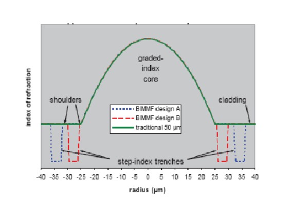
Figure 13 Conventional 50μm multimode fiber bend insensitive MMF, and two cross-sectional view BIMMF

 OM4 Multimode Fiber

The Multimode Fiber Proucts on market

 FC-FC Duplex OM1

FC-FC Duplex 62.5/125 OM1 Multimode Fiber Patch Cable

FC-SC Simplex OM2

FC-SC Simplex 50/125 OM2 Multimode Fiber Patch Cable

BIMMF bend-insensitive fiber mode field shown in Figure 14: In the conventional multimode fiber MMF, the guided mode in strong low conductivity state, and in close proximity to the core - cladding interface propagating order modes, because the effective refractive index neff close to the refractive index of the cladding n2, it is weakly conducting state (when the guided mode is equal to the effective refractive index neff cladding refractive index n2, the mode cutoff). Conduction state is weak order modes in the fiber bend radius is too small, its intensity will escape the core, causing signal distortion. In the bend-insensitive fiber BIMMF ring depressed trench type refractive index distribution has two light guide interface, the refractive index in the descending interface, the interface to form a light guide. Because of this interface, enhanced guided mode fiber core conductivity, so that the original order modes weak to lead the state into a strong lead state, shown in Figure 14. In addition, the external interface subsidence ring groove type refractive index distribution of the refractive index of small to large, the formation of refractive interface. Since the refractive index profile of this special structure, there is a leakage conductivity mode (leaky mode) in BIMMF fiber. Leakage mode is the solution of the equation in the intrinsic region outside the cutoff, leaky guided mode parsing mode is outside the cutoff continuous, their field is the same, but its intrinsic value, or the propagation constants are complex solutions Eigenequation, thus There are inherently leaky mode attenuation can not normally spread dissemination. The effective refractive index neff leakage mode of the cladding is less than n2. In the conventional multi-mode fiber, a leaky mode consumption decline rapidly, since the refractive index of a conventional optical fiber structure can not support its propagation in the fiber. And it BIMMF fiber, the refractive index in the form of this particular cross-sectional structure, a strong core to maintain close - cladding interface order modes propagating conductivity, thus effectively improve the flexural properties of the fiber.

2014年5月22日星期四

The Technical Characteristics And Application Prospect Of New Generation Multimode Fiber

As we all know , due to the use of the Internet, the data transmission requirements show explosive growth like a geometric progression, so the network transmission speed requirements are also increasing intensity. The multi mode fiber is concerned , due to its inherent properties , it is generally used in a LAN , storage network , data center. In these areas , the data transmission rate of exchange is also required to continue to grow . To Ethernet , for example, since the 1990s , the transmission rate from 10Mbit / s ( Ethernet ) to 100Mbit / s ( Fast Ethernet ). IEEE in 1998 by the IEEE802.3z of Gigabits Ethernet (GbE) standard . 10Gigabit Ethernet standard IEEE802.3ae also passed in June 2002 . Multimode fiber products have been defined by the standard Ethernet transmission medium, its transmission window is at 850nm and 1300nm. Current land use in a communications network products for the general multimode A1a (50/125um) and A1b (62.5/125um) two kinds. Both products are performance and calibration of Ethernet and Fast Ethernet compatible. Just GbE Ethernet and 10GbE Ethernet standard is concerned , A1a and A1b multimode product is not suitable. Mainly due to the modulation frequency of LED (light emitting diode ) light source, only a maximum of about 650MHz. So Gbit / s and 10Gbit / s Ethernet must use LD ( laser diode ) as a light source, such as VCSEL ( vertical cavity surface emitting laser ) light source . This change makes the light A1a and A1b multimode fiber show a mode dispersion problem, the transmission distance can not meet demand. Therefore, it needs to improve the multimode fiber manufacturing technology , development and manufacturing of new generation of multi -mode fiber . This article describes a new generation of technical characteristics and application prospects multimode fiber.

Generally, there are many index to impact multimode fiber performance, but the direct result to the transmission distance is mainly affected by attenuation and multimode fiber bandwidth parameters. The attenuation parameter is determined by the fiber structure and the dopant concentration, the new generation of Multimode Fiber Patch Cable is same with the original fiber optic calbe on the product structure. so they are the same attenuation indicators . Multimode fiber bandwidth uses MHz.km units. It is the modulation frequency and the length of the fiber product of the maximum modulation frequency of the pulse period of the optical fiber which can pass through. Because bandwidth is a comprehensive index multimode fiber characterization of the optical properties, it is affected by many factors, such as the light source, coupling waveguide structure, as well as the receiver performance aside other factors, on the fiber itself, determine its bandwidth intrinsic factor is a multimode fiber dispersion properties. Discussing multimode fiber dispersion analysis generally two ways, i.e., inter- mode dispersion and chromatic dispersion. That is, since the chromatic dispersion of the transmission of different wavelengths of light caused. Mode dispersion refers chromatic dispersion due to the different transmission modes caused. The essential difference between the ordinary and the new generation of multi -mode optical fiber is a multimode optical fiber being derived from this.

Optical Fiber
 Figure 2
 Multimode fiber

For Common multimode fiber, since the LED light source are intended to be used in a network system. LED light source is a wide spectrum of areas having a large output. Due to its broad spectrum of characteristics, emitted light have different wavelength components, when such a light pulse is transmitted in the optical fiber, dispersion is the main cause of chromatic dispersion. The new generation of multi-mode fiber optic network is expected to be used in the LD light source. LD is a single-wavelength laser light source, the LD so emitted light pulse transmitted in the multi-mode fiber, dispersion-mode dispersion will be the main cause.

The related proucts about Common Multi-mode Fiber Optic Cable from Fiberstore, SC-SC Simplex 62.5/125 OM1 Multimode Fiber Optic Cable,

OM1 SC SC Multimode Fiber Patch Calbe

At the same time, because the common manufacturing process multimode fiber defects appear in the center of the center "recess", this defect is due to the dopant material, such as a transition caused by evaporation of germanium. While multimode fiber interface, i.e., between the fiber core and cladding is easy due to the diffusion of dopant materials such defects. These defects in the original multi-mode fiber is not important. But for a new generation of multi-mode fiber is fatal. These defects will greatly increase the inter-mode dispersion and reduce the transmission properties of the optical fiber.

For the light source, the table 1 is a comparison of a typical LED light source and a VCSEL. it can be found, VCSEL is much less than the spectral width of the spectral width of the LED, so the purpose of comparison to the LED, LD can be said that the injection of a single wavelength. The LED and light emitted from the LD of different spot size. LED exit a larger area, you can inspire all of multimode fiber conduction mode, while LD light spot emitted only a small part inspired conduction mode. When injected into the LD multi-mode fiber end faces at different locations, different mode groups are excited, it will make the inter-mode dispersion and a greater difference between the transmission distance of the impact pulse. Figure 4 shows a comparison of light output LED and a VCSEL.

Injection method means the energy emitted by the light source is coupled into the multimode fiber process. Generally limited to full injection and injection molded in two ways. When the LED light source is a full injection, i.e., spot size, and light emitted from the multimode fiber core sizes are matched, then the pulse is excited in the multimode fiber optic cable conduction mode transmission, the transmission energy is concentrated in the middle mode group. While limiting the injection mold, the incident light spot covers only a part of the core, when it is conducting, it is only part of the excitation conduction mode groups. When the incident light spot at different positions of the core, the excited mode groups are different, resulting in differences in the inter-modal dispersion such that the bandwidth performance of the change of the transmission fiber. Therefore, when injected into the mold limit, you must determine the position and angle of the incident, otherwise the transmission distance of fiber support will change.

In IEEE802.3z GbE Ethernet standard, for the laying of fiber optic cable has proposed a so-called Patch cord [4] solution is injected into the mold of a typical limit program. In the 1300nm wavelength, this solution uses a single mode fiber as shown bias limit injection molding conditions, this Single Mode Fiber Cable can not only reduce multi-mode fiber optic which conduction mode is excited, but also partial connection set. It can avoid larger centers may exist in the optical fiber embedded in a recess problems.


 Multimode Fiber Calbe

The above shows that the use of ordinary multimode fiber at Gbit / s and 1010Gbit / s Ethernet system, the light source, injection method and fiber itself, it will greatly deteriorate the performance of optical fiber transmission, increase system overhead, or increase system complexity. To solve these problems, the development of a new generation of suitable Gbit / s transmission rate over multimode fiber using a local area network products are the best choice. The new generation multimode fiber products from Fiberstore, you can find the related products, MPO MTP Fiber. MPO/MTP Fiber Cable is offered for many applications for all networking and device needs like 100 Gig modules. MPO Fiber Cable From Fiberstore are available in UPC and APC finishes, it supports both multimode and single mode applications, and optional lengths available. Our MPO/MTP fiber cable is with push connector IEC 61754-7 and TIA/EIA 604-5A compliant and offer low cost per termination for high density applications.

2014年5月20日星期二

Dispersion And Types of Multimode Fiber

Multimode optical fiber dispersion is the time of the different modes in a multimode optical fiber transmission difference generated, because there are many mode of multimode fiber, the resulting dispersion is more complicated. So multi-mode optical fiber is not used as a dispersion single-mode fiber to characterize the dispersion properties of the coefficient. Multimode Fiber Cables with dispersion characteristic pattern "Bandwidth " to indicate that the " bandwidth" of the multi-mode fiber, it means the ability of a transmission signal in units of MHz * Km, refers to the product of speed and distance , low rate the transmission distance and high- speed transmission distance is near . With a "Bandwidth " associated with the type of light source used for multimode fiber. Different types of light sources with the same optical fibers obtained by the test "Bandwidth " is different, the bandwidth of a multimode optical fiber with the general terms of use. Different types of light emission characteristics of the injection for reasons multimode fiber mode excitation type : LED can excite all modes, this light is called test OFL (overfilled launch) testing. FP and VCSEL lasers with multi-mode fiber can stimulate injection -mode optical fiber portion , such tests are called UFL (underfilled launch) Test This test out several light sources "bandwidth " is different .

Species historically commercialization of multimode fiber is very large, there are different classification methods, the current standard is more popular in the beginning of 2002 classification ISO / IEC 11801 enacted.

ISO / IEC standard classification simplifies multi-mode fiber. The old 62.5um fiber referred to as OM1 fiber, 50um fiber referred to as OM2 fiber. Emerging mode dispersion optimized fiber were divided by the bandwidth of the OM3 and OM4 fiber. Both fiber bandwidth in the EMB (Effective Modal Bandwidth) conditions were greater than 2000MHz * K and 4700MHz * Km, corresponding to the conditions of use that source using 850nm VCSEL.

Common 62.5/125μm graded-index OM1 Multimode Fiber is the iec-60793-2 fiber optic products specification alb type. It was born in the late -index multimode fiber 50/125μm gradient. As the core diameter and a numerical aperture of the fiber 62.5/125μm larger , with a strong light gathering capability and bending characteristics , especially in the 20th century, before the mid-1990s , the lower the rate of the LAN , less demanding on the fiber bandwidth thus making this fiber to obtain the most widely used, becomes 20 years between the mid- 1980s to the mid -1990s mainstream products in most countries data communications fiber market. 62.5/125μm graded-index multimode fiber is the first to be adopted as the United States a number of industry standard multimode fiber , such as interior wiring systems standards at & t 's ; American Electronics Industry Association (eta) LAN standards ; American National Standards institute (ansi) of 100 mb / s token Ring standards ; ibm token ring standards. Typically 62.5/125μm graded-index multimode fiber bandwidth is for 200 ~ 400 mhz · km, at 1 gb / s rate , 850 nm wavelength transmission 300 m, 1 300 nm wavelength transmission 550m. Full power injection (OFL) bandwidth of 200/500 MHz.km @ 850/1300 nm.

Common 50/125μm graded-index OM2 Multimode Fiber is the iec-60793-2 fiber optic products specification ala type. Historically, in order to reduce system costs as much as possible LAN, commonly used inexpensive led as the light source, rather than expensive ld. Because of the low output power led, ld much larger than the divergence angle connector loss, and 50/125μm multimode fiber core diameter and numerical aperture are relatively small, it is not conducive to the efficient coupling and led, as the core diameter and numerical aperture the 62.5/125μm (class alb) fiber enables more light power coupled into the fiber link to, therefore, 50/125μm graded-index multimode fiber in the mid-1990s, had not been widely used, and is mainly used as a data communication standard in Japan and Germany.

At a rate of 10Gbps, 850nm VCSEL can only guarantee the transmission distance of about 30m in the worst OM1 fiber, in the latest OM4 fiber transmission distance of 550m of guarantees. 850nm VCSEL have a high luminous efficiency, low threshold, high modulation rates can be easily coupled and so on. The main source is the use of multimode optical fiber, OM3, OM4 fiber is mainly optimized for 850nm VCSEL mode dispersion.

Each VCSEL coupled into the modes of the multimode fiber are not identical, therefore, a multi-mode Fiber Optic Patch Cables with a difference of each VCSEL "bandwidth", the performance is often much longer than the transmission distance of the optical fiber shown in a nominal bandwidth. In multimode fiber using FP or DFB guaranteed transmission distance is not as 850nm VCSEL, but does not exclude an individual can transmit very far situation.